
Short answer: for a turned shaft, 1144 Stressproof steel can be a useful starting condition when the drawing needs a strong, machinable bar and the stock certificate confirms the specified product. Do not treat every 1144 bar as Stressproof: grade, cold-finished condition, stress relief, diameter, and supplier certification all affect what arrives and how it behaves after material is removed. A sound 1144 stressproof steel machining plan therefore begins with the purchase specification and the part’s datum scheme, then controls how asymmetric features release stress.
The practical risk is often not cutting force alone. A shaft that is straight as supplied can move after a keyway, cross-hole, flat, or deep pocket removes material from one side. Plan the sequence around the finished axis and inspect the free-state part after the final cut.
Confirm the bar condition before programming
“1144” identifies a resulfurized medium-carbon steel grade; “Stressproof” is a trade name associated with a particular cold-finished, stress-relieved bar product. The terms should not be used interchangeably on a purchase order. Specify the required grade, product form, applicable bar specification, supplied condition, and documentation. If the drawing relies on strength or straightness, obtain the mill test report and confirm that the ordered product actually matches the design assumption.
This distinction changes how a machinist interprets movement. A stress-relieved product may reduce residual-stress surprises compared with an unspecified bar, but it cannot guarantee that every finished geometry remains straight. Cutting still changes the balance of material around the axis. For general selection context, the site’s steel materials overview is the parent reference; the exact product condition must come from the drawing and material paperwork.
Let the shaft geometry set the cut sequence
Start by separating features that establish the shaft’s functional axis from features that remove material asymmetrically. Turn the principal diameters and shoulders from a controlled datum, then evaluate how much stock remains around the centerline before adding flats, keyways, or radial holes. For a long or slender part, support and overhang matter: a steady rest, tailstock support, or staged workholding may be appropriate, but the setup must not force the blank into a shape it will not hold when released.
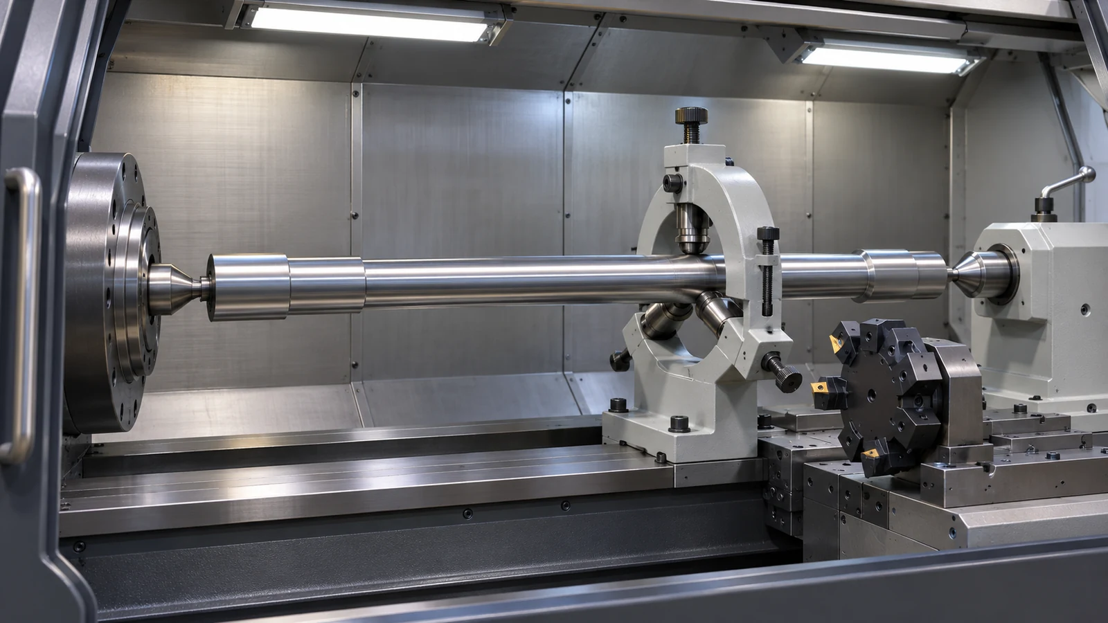
A practical sequence often uses rough turning, a release and inspection check, then finish turning after the blank has settled. That is not a universal recipe: short, balanced parts may not need an intermediate release, while a long shaft with an off-center feature may need several controlled steps. The useful question in 1144 stressproof steel machining is not “Which canned cycle is best?” but “Which cut changes the material balance most, and when can the part be measured without fixture load?”
Treat keyways and cross-features as stress releases
A keyway or milled flat removes a strip from one side of a round section. A cross-hole removes material through the section and can also create burrs at both exits. Put these operations where the part can be supported repeatably, and avoid clamping across a thin wall or a finished bearing seat. If milling follows turning, preserve the turned datum in the fixture rather than re-centering from an unrelated surface.
For a feature that controls assembly, define its relationship to the axis explicitly: position, angular orientation, width, and any fit requirement should be unambiguous. If the part must mate with a hub, use the drawing to identify whether the keyway or flat is the locating feature or merely a torque-transfer feature. This prevents a shop from inferring function from a sketch. Standard CNC turning is relevant to the axis and diameter work; milling details should be specified where the cross-features require them.
Inspect the free state, not only the chuck setup
Measure straightness, runout, and critical diameters after releasing the part from the fixture. A part can appear true while clamped and shift when unclamped. For shafts with separated journals, record the datum axis and indicate the functional surfaces from that axis. Where the drawing calls for a straightness or runout tolerance, inspect at a defined support condition so the measurement does not introduce its own sag or distortion.
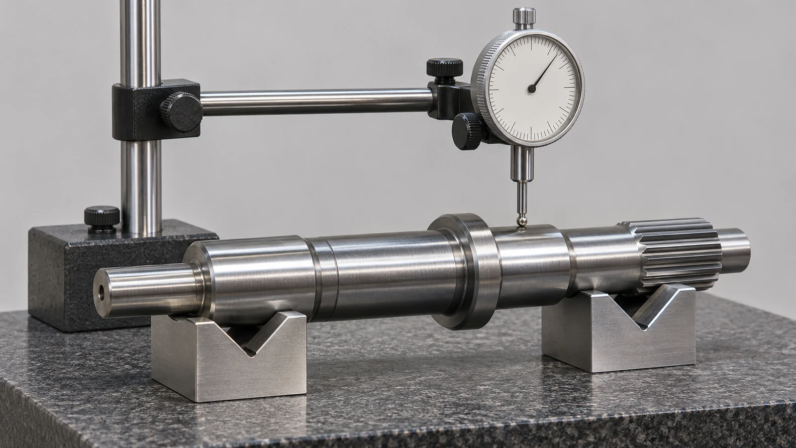
Do not infer acceptance from a material name or a supplier’s typical property table. The drawing controls. Record the incoming condition, operation sequence, intermediate checks, and final free-state result when movement would affect fit. If a part drifts after a one-sided feature is cut, review remaining stock, fixture pressure, tool deflection, and datum transfer before changing nominal dimensions.
What to put on the drawing and RFQ
Identify the required 1144 product condition and documentation; show the finished axis, journal diameters, shoulders, keyways, flats, cross-holes, and their datum relationships; and state which surfaces control assembly. Include the required inspection method for runout or straightness and whether the part is measured free or under a defined support. If a specific Stressproof-branded product is required, say so explicitly rather than using the trade name as shorthand for all 1144.
For a machinist, that information determines whether the process can preserve the part’s functional axis through turning and secondary milling. A drawing that makes condition and datums explicit is more useful than a generic note that the part must be “precision machined.” That is the practical boundary of 1144 stressproof steel machining: verify the stock, plan the asymmetric cuts, then accept the released part against its functional datum.