
Valve body machining datum selection should begin with the interfaces that locate the valve in its assembly and control the flow path. A datum scheme that is convenient to clamp may still mislocate a spool bore, seat pocket, port face, or cover interface. The goal is to carry one defensible reference system from the drawing through machining and inspection, while keeping pressure-boundary and sealing requirements tied to the actual design.
Because valve architectures differ, there is no universal datum order. A directional valve with a precision spool bore, a compact cartridge body, and a manifold-style block do not necessarily share the same functional references. Start from the part’s mating components and released drawing rather than importing a standard fixture scheme.
Read the part as interfaces, not as a block
Mark the features that establish location: mounting face, port pattern, cartridge or cover seat, spool bore, dowel holes, and any external pilot. Then identify which features are connected by assembly function. For example, a port face may locate the body to a manifold while a bore axis controls an internal moving element; the drawing must explain how their relationship is accepted.
Separate features that seal from features that locate. A flat gasket land may need a surface or form requirement, while a bore may need size, form, and position controls relative to a functional datum reference. Treating every face as equally important can create an overconstrained drawing without improving how the valve assembles.
Choose a datum scheme that can be reproduced
Valve body machining datum selection is useful only if the datum features can be contacted consistently in the setup and in inspection. A broad mounting face may establish a primary plane; a port pattern, pilot, or bore may establish location and rotation depending on the design. Select the sequence from the assembly constraints and make the controlled relationships explicit.
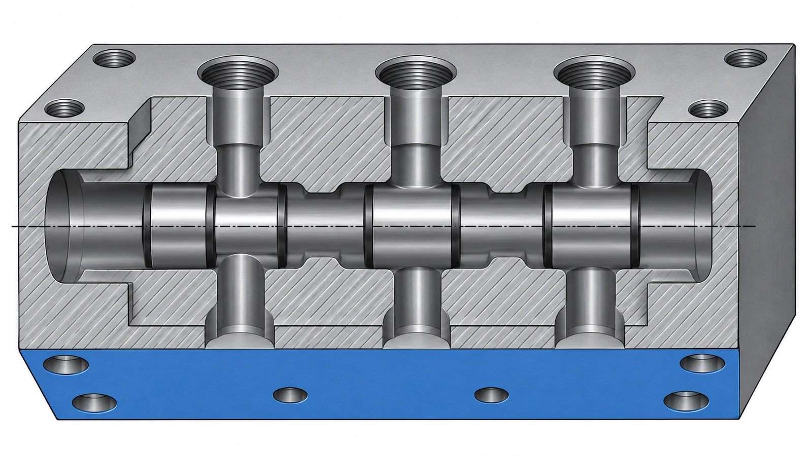
For a body with intersecting passages, distinguish the external datum scheme from internal feature relationships. The port entrances, cross holes, and bore intersections may require positional controls, but a datum does not by itself define the required flow area or guarantee hydraulic performance. Those acceptance criteria belong in the engineering specification.
Translate the drawing into a machining sequence
Plan roughing and finishing around stock stability, access, and datum transfer. If the critical bore and its locating face can be completed from a common setup without compromising tool access or part support, that may reduce reference transfer. If multiple setups are needed, define how a finished datum is picked up again and how clamping avoids distortion.
Small cross holes and intersecting passages can leave burrs or edge conditions that matter to assembly and cleanliness. The drawing or process notes should state which edges require deburring and which sealing or seating edges must remain protected. Do not use an unspecified “break all edges” note where it could change a sealing land or alter a critical port entrance.
Where milling is part of the plan, the site’s CNC milling capability page provides the relevant process context. The final operation sequence still depends on the body geometry, material condition, drawing tolerances, and inspection access.
Make inspection follow the same reference logic
Inspection should simulate the stated datums and report the features that drive assembly: bore size and form, port and mounting-face relationships, seat position, and sealing-land condition as required. A CMM can evaluate defined geometric relationships when probes can reach the features; dedicated gauges may suit repeated checks if their locating scheme matches the drawing.
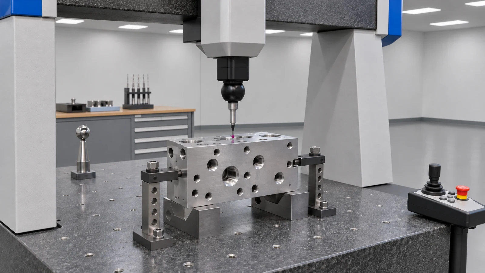
Before release, review how the part is supported during measurement. Thin walls, asymmetric clamping, or a long setup stack can shift readings. Record the datum simulators and measurement condition so manufacturing and receiving inspection are not judging the same tolerance from different reference frames.
Questions to resolve before the first article
- Which interfaces locate the body in the actual assembly?
- Which bore, seat, port, or face relationships are functionally controlled?
- How are sealing lands and edges protected during machining and deburring?
- Does each critical feature remain accessible in the selected inspection setup?
- Are pressure, leakage, cleanliness, or flow tests assigned to a defined party?
A sound datum plan gives the drawing, fixture, and inspection method the same interpretation of the valve’s locating chain. Valve body machining datum selection should therefore be reviewed with the mating manifold, cartridge, cover, and acceptance plan in view—not chosen solely because one face is easy to clamp.