
Machined contact pin plating allowance must be defined from the finished electrical and mechanical interfaces, not added as an arbitrary machining offset. A pin may need a controlled mating diameter, shoulder location, insertion length, and contact zone after plating. The drawing should identify which dimensions apply before finishing, which apply after finishing, and how the plating boundary is established.
The required buildup depends on the selected plating system, specification, contact function, and process capability. There is no single allowance that can be applied safely to every pin. The CNC supplier can machine the component to the agreed pre-finish geometry; plating responsibility and final acceptance should be assigned explicitly.
Map the functional zones on the pin
Divide the part into zones: the electrical contact area, press-fit or sliding interface, shoulder and stop, retention features, and any nonfunctional handling region. A coating may be required only on selected surfaces. The drawing should show the plating extent and any keep-out areas so that the supplier and finisher do not infer the boundary from appearance.
Then identify dimensions that control the mating assembly. For a plated diameter, state whether the tolerance applies to the substrate before plating or the finished outside diameter. For a shoulder, groove, or insertion length, clarify whether coating buildup is included in the final dimension. This prevents a nominally correct machined blank from becoming an out-of-tolerance finished contact.
Calculate buildup from the specified process
Machined contact pin plating allowance is a process-dependent design input. If a coating is deposited on a cylindrical surface, the final diameter changes with buildup on both sides; edges, recesses, and complex geometry may receive a different distribution. The specified minimum and maximum thickness, measurement method, and applicable standard should come from the design authority or approved finishing specification.
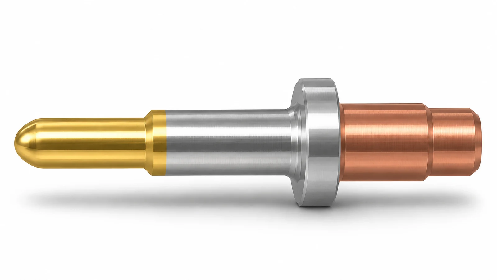
Do not convert a typical thickness from a supplier brochure into a universal machining offset. Deposition method, rack position, geometry, masking, and process controls can change local results. Where final fit is tight, coordinate the plating supplier’s capability and measurement method before freezing the substrate dimensions.
Control boundaries, threads, and contact faces
Masking and selective plating can affect where coating begins, how an edge looks, and whether a transition interferes with assembly. Call out the boundary using a clear datum, dimension, or drawing view. Also identify whether threads, internal bores, sharp corners, or press-fit zones are plated, protected, or finished after coating.
Contact performance is not determined by thickness alone. The specified material, finish, cleanliness, mating force, and operating environment also matter. Avoid making electrical resistance or durability claims unless the design has a defined test and acceptance requirement. The site’s machined EV connector components page gives related part context, while surface finish options should be reviewed only against the project’s actual finishing scope.
Plan inspection around the final state
Inspection should state whether the pin is measured as-machined or after plating. If the final diameter is the acceptance feature, measure the finished surface using an agreed method and instrument suitable for the geometry and coating. If the substrate is also controlled, keep separate records for pre- and post-finish dimensions rather than treating one result as proof of both.
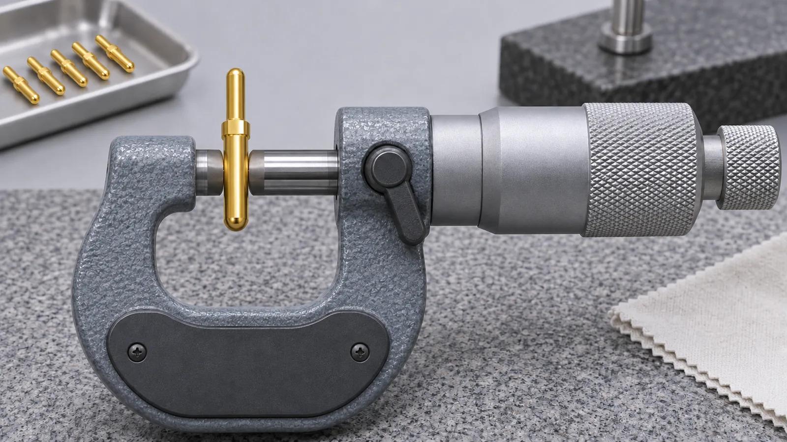
Machining and finishing suppliers should agree how parts are identified through the handoff, how masked regions are checked, and how nonconforming buildup is handled. For small pins, handling and contact marks can also affect the evaluation surface, so the inspection plan should define cleaning and measurement conditions when needed.
Release checklist for a plated contact pin
- Mark plated, unplated, and masked zones on the drawing.
- Identify dimensions that apply to the substrate and those that apply after plating.
- Reference the approved plating specification, thickness range, and measurement method.
- Review threads, shoulders, grooves, and mating diameters for buildup effects.
- Assign responsibility for plating, boundary control, final inspection, and records.
A useful machined contact pin plating allowance is therefore the result of a defined finish process and a clear final-part requirement. Set the substrate dimensions only after the coating system, tolerance state, and inspection responsibility are agreed; otherwise, the word “allowance” hides several different assumptions.