
A transparent PMMA housing leaves the CNC machine with the correct outside dimensions. The drawing says the part should work. Yet under inspection, its edges look milky, one drilled hole shows a fine crack, the pocket contains visible cutter marks, and polishing adds far more labor than expected. This is one of the central challenges of acrylic PMMA machining: producing the shape is often easier than producing the shape, clarity, dimensional stability, and cosmetic finish at the same time.
For an engineer or buyer, this difference matters. PMMA may look like a straightforward plastic, but it reacts strongly to heat, tool sharpness, clamping pressure, chip evacuation, machining sequence, stress, and finishing. A process that works well on aluminum may damage acrylic within seconds. A process that produces an acceptable prototype may also become expensive or unstable when quantities increase.
The solution is not simply to slow the machine, increase spindle speed, or polish every surface afterward. Reliable PMMA production requires a complete machining strategy in which material grade, equipment, cutters, feeds, fixturing, roughing, finishing, inspection, and post-processing work together.
This guide follows that manufacturing problem from failure to solution. It explains how the process works, which machines and tools may be suitable, why transparent parts fail, how to establish a practical production procedure, where PMMA is commonly used, and what buyers should evaluate before selecting a CNC supplier such as JUCHENG.
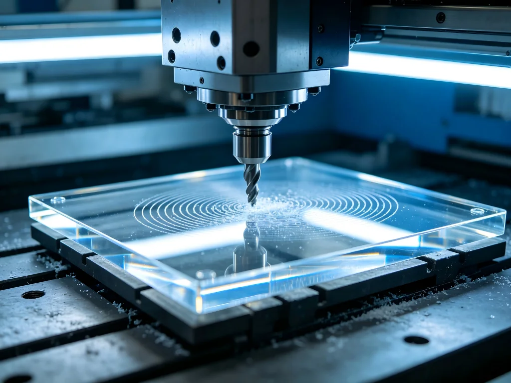
The Real Problem: A Clear Material Exposes Manufacturing Mistakes
Many CNC defects can hide on an opaque engineering component. Tool marks on the inside of a black POM enclosure may have little effect on its commercial value. Minor cosmetic differences on an aluminum bracket may disappear after anodizing.
Transparent acrylic behaves differently because the customer can see the manufacturing history.
Tool marks are visible. Chipping is visible. Internal stress may eventually become visible. Poor polishing is visible. A small scratch caused by careless handling can remain obvious after the component passes dimensional inspection.
This means that PMMA manufacturing often involves three separate definitions of quality:
- Geometric quality: Are dimensions, holes, pockets, radii, flatness, positions, and assembly interfaces correct?
- Surface quality: Are machining marks, scratches, edge chips, burrs, haze, and polishing defects within the agreed cosmetic standard?
- Material integrity: Has machining introduced excessive heat, stress, cracking, or other conditions that could cause later failure?
A supplier could satisfy the first requirement while failing the other two.
That is why a professional acrylic CNC project should not begin with the question, “What tolerance can your machine hold?” It should begin with a broader question: “What does this component need to do after machining, finishing, assembly, cleaning, and real-world use?”
What Is PMMA and Why Does Its Behavior Matter?
PMMA is polymethyl methacrylate, a transparent thermoplastic commonly called acrylic. Commercial users may also recognize names such as acrylic glass, Plexiglas, Perspex, or Lucite.
Its main engineering attraction is the combination of transparency, rigidity, low weight, weather resistance, design flexibility, and machinability. Depending on grade and application, PMMA can provide an attractive glass-like appearance without requiring the manufacturing methods associated with conventional glass.
CNC machining makes the material even more useful because engineers can create more than flat profiles.
A machining center may produce:
- precision pockets and cavities;
- mounting holes and counterbores;
- channels and flow paths;
- threads and insert features;
- curved or three-dimensional surfaces;
- optical and lighting features;
- engraved markings;
- multi-face housings;
- prototype lenses and light-management components;
- complex transparent engineering assemblies.
This creates an important bridge between prototyping and production. A development team may machine several versions of a transparent component without committing to injection-molding tooling. CAD changes can be introduced quickly, tested, measured, and revised.
However, PMMA’s thermal and mechanical behavior explains why process control is so important.
Metal conducts machining heat away from the cutting zone relatively efficiently. Acrylic does not behave in the same way. If heat builds around the cutter, the polymer may soften. Once softened material sticks to the cutting edge, tool performance can deteriorate rapidly. Instead of creating a clean chip, the tool may begin rubbing, smearing, or recutting softened material.
The operator may then see exactly the symptoms that buyers complain about: melted edges, gummy chips, white surfaces, dimensional variation, rough walls, or a cutter that appears to be covered with plastic.
Reliable machining therefore depends on creating a chip and getting that chip away from the workpiece.
Failure No. 1: The Acrylic Melts Instead of Cutting Cleanly
Melting is probably the most discussed acrylic CNC problem because it creates an immediate and obvious failure.
An operator opens the machine door and finds material wrapped around the end mill. The edge looks smeared rather than crisp. Small chips have turned into stringy or welded deposits. Surface quality collapses.
The intuitive response is sometimes to reduce the feed because slower movement feels safer.
That can make the problem worse.
If the spindle continues rotating quickly while feed becomes very low, each cutting edge may remove too little material. Instead of producing a useful chip, the cutter spends more time rubbing the polymer. Friction generates heat. The material softens, adheres to the tool, and produces still more friction.
The important relationship is therefore not spindle speed alone and not feed rate alone. It is the relationship between cutter geometry, number of flutes, spindle speed, feed, engagement, material, and chip formation.
How the Process Should Be Corrected
A stable cutting strategy generally tries to make a defined chip, evacuate it efficiently, and prevent hot material from being recut.
The exact parameter window depends on the machine, cutter diameter, flute count, rigidity, feature geometry, depth of cut, PMMA grade, and finish requirement. There is no universal RPM value that works for every project.
However, several process principles remain useful.
The cutter should be sharp. Tool geometry should support plastic cutting and chip evacuation. The feed should be sufficient for the cutter to cut rather than rub. Tool engagement should not create unnecessary heat. Chips should leave the cutting zone quickly. Air blast or an appropriate cooling approach may assist chip evacuation where the process and material specification permit it.
Online CNC communities frequently describe the same pattern. Users often report that moving from general-purpose multi-flute tools to suitable single-flute or O-flute cutters, while maintaining proper feed and clearing chips with air, can transform acrylic machining from a melting problem into a clean cutting operation.
This user experience makes sense mechanically. A large flute space gives chips somewhere to go. A sharp edge reduces rubbing. Effective evacuation reduces recutting. The result may be lower heat accumulation and more consistent walls.
Failure No. 2: The Dimensions Are Correct but the Part Looks White
Cloudy edges and milky machined surfaces create another confusing situation.
The buyer may receive a part that is technically transparent when viewed through untouched stock surfaces, yet every machined wall looks white or frosted.
This is not necessarily evidence that the material itself is poor.
A machined surface contains microscopic cutting marks. These irregularities scatter light. The more irregular the surface becomes, the less optically clear it appears.
Excessive heat can make the problem worse, but even a stable milling operation does not automatically create an optical-grade transparent surface.
This distinction is essential when specifying a part.
“Clear PMMA” describes material.
“Optically clear machined surface” describes an outcome that may require dedicated machining and finishing.
Start With a Better Machined Surface
The most economical polishing process begins with good machining.
Suppose one supplier aggressively roughs an outside wall and leaves deep cutter patterns. A technician may need substantial sanding and polishing to remove them.
Another supplier separates roughing and finishing. The roughing operation leaves a controlled allowance. A sharp finishing cutter then removes a small amount of material under stable conditions and produces a more uniform wall.
Both parts may eventually look clear.
But the second route could require much less secondary labor and may preserve geometry more reliably.
This is especially important because polishing removes material. A supplier cannot indefinitely improve appearance without considering dimensional change, edge shape, flatness, and local geometry.
For tight-tolerance transparent components, machining and finishing therefore need to be planned as one manufacturing system rather than independent departments.
Failure No. 3: A Hole Looks Fine Today and Cracks Later
Delayed cracking can be more dangerous than an obvious machining defect because the part may already have passed inspection.
A transparent housing could leave the factory with clean dimensions and a good visual appearance. After screws are installed, transported, cleaned, or exposed to a chemical, fine cracks may begin forming around a hole or stressed edge.
This type of failure highlights the role of residual stress.
Stress can come from raw material production, aggressive machining, poor drilling conditions, clamping, thermal effects, polishing, bonding, or final assembly.
Design can add another layer of risk.
A small hole located too close to an edge creates a more fragile region. A countersunk screw may generate high local stress. A fastener tightened as if the housing were aluminum can overload the polymer. A rigid metal frame may constrain thermal movement.
In other words, PMMA cracking should not automatically be blamed on “bad plastic.”
The root cause may involve material, machining, design, assembly, or chemical exposure.
A More Reliable Drilling Strategy
Drilling should be treated as a controlled cutting operation rather than forcing a conventional drill through clear sheet or block material as quickly as possible.
A suitable tool geometry can reduce stress at the cutting edge. Chip removal is important because packed chips add heat. Breakthrough deserves special attention because unsupported material around the exit may chip.
For critical holes, the manufacturer may use a staged process or machine the feature by milling rather than conventional drilling, depending on diameter, geometry, tolerance, wall thickness, and equipment.
The PLEXIGLAS processing guidance also emphasizes that the drill itself is not necessarily the deciding factor; the cutting geometry of the drill bit is critical for producing accurate acrylic holes.
This leads to a practical purchasing question:
Instead of asking a CNC shop only whether it can drill the hole, ask how it plans to machine, inspect, and protect a high-stress hole in a clear component.
Cast Acrylic or Extruded Acrylic?
Before the CNC program is created, the raw material choice can already affect the outcome.
Cast and extruded PMMA are both acrylic, but their manufacturing history and machining behavior differ.
Cast acrylic is often selected for demanding CNC applications because it generally offers favorable machining characteristics, optical quality, and thermal behavior. Extruded acrylic can offer consistent sheet thickness and potentially lower material cost for appropriate projects, but it can be more sensitive to heat and internal stress during machining.
That does not mean extruded material is unusable.
It means the material should follow the application instead of being chosen only by unit price.
| Decision Area | Cast PMMA | Extruded PMMA | Buyer Consideration |
|---|---|---|---|
| Precision CNC Machining | Often preferred for demanding machining | Can be machined with controlled parameters | Consider geometry, stress and finishing needs |
| Optical / Cosmetic Work | Strong choice for high-end transparent parts | Suitable for many general transparent parts | Define actual optical requirement |
| Thermal Sensitivity During Cutting | Generally favorable machining behavior | May require closer heat control | Supplier process experience matters |
| Sheet Thickness Consistency | May show more production-related variation | Often offers consistent sheet thickness | Relevant for sheet-based designs |
| Cost Priority | May cost more depending on grade | Can be economical for suitable applications | Compare total manufacturing cost, not stock price alone |
| Complex Machined Optical Part | Frequently the safer starting point | Requires application review | Prototype before volume production |
| Simple Window or Panel | Suitable | Often suitable | CNC may not always be the lowest-cost process |
JUCHENG’s PMMA material guidance places particular emphasis on cast acrylic for precision parts such as optical components, light guides, medical manifolds, and premium transparent products.
For a buyer, this is a useful example of why an RFQ should state more than “acrylic, clear.”
If the engineering team already knows the required grade, include it. If it does not, describe the function, environmental conditions, surface requirement, and volume so the machining supplier can discuss appropriate options.
The Acrylic PMMA Machining Process: From CAD to Clear Part
A robust process is easier to understand if we follow the component through production rather than treating milling, polishing, and inspection as unrelated operations.
Stage 1: Review the Design Before Material Is Cut
The first manufacturing decision should happen at the CAD stage.
A supplier should examine wall thickness, pocket depth, tool access, internal radii, drilling geometry, hole-to-edge distance, threads, surface finish, tolerance distribution, undercuts, and visible surfaces.
This DfM review can prevent expensive mistakes.
For example, an engineer may specify a perfectly sharp internal corner because the CAD software makes it easy to draw. A conventional round end mill cannot create that corner directly. The supplier may need a smaller cutter, another process, a design change, or a relief feature.
Similarly, a very deep narrow transparent pocket may look simple in CAD but require a long slender cutter. Tool deflection and vibration could then damage wall quality.
The correct question is not, “Can CNC make this?”
Modern machining can produce remarkably complex geometry.
The better question is, “Can it be made repeatedly, economically, and at the required quality?”
Stage 2: Verify the Raw PMMA
Material identity should be confirmed before production.
For quality-sensitive projects, traceability may become important. Medical, automotive, analytical, and regulated applications may require documentation that connects the finished component with the specified material source or batch.
The stock should also be checked for scratches, contamination, surface damage, thickness, or other conditions that could affect final appearance.
This matters because transparent components are unusually sensitive to handling.
A machining center cannot remove a deep scratch from an untouched optical face unless that face is intentionally refinished.
Stage 3: Plan Workholding
The workpiece must be held securely enough to resist cutting forces but not so aggressively that the fixture becomes part of the problem.
Several approaches may be appropriate:
- soft jaws shaped around the component;
- vacuum workholding for sheet-style geometry;
- sacrificial support plates;
- custom fixtures;
- low-distortion clamping;
- tabs or temporary material features;
- multi-operation fixtures designed to protect cosmetic faces.
The method depends on geometry and quantity.
A thin transparent plate and a thick optical block should not automatically use the same fixturing strategy.
For production runs, dedicated fixtures may add initial cost but improve consistency and reduce handling time. For one-off prototypes, more flexible workholding may be economical.
Stage 4: Select Tools for the Material
Acrylic machining is one of those applications where cutter selection can change the entire process.
The objective is a sharp cutting action with enough flute space to carry chips away.
Single-flute and O-flute cutters are common choices in plastic machining because their geometry may support efficient chip evacuation. Depending on machine, geometry, and finish requirements, other carbide tools may also perform well.
The important point is that the tool should be selected for the operation.
A roughing tool is solving a different problem from a finishing cutter.
A drill is solving a different problem from an end mill.
A tool used for a transparent final wall should not automatically be treated the same way as a tool removing bulk stock from an invisible pocket.
Stage 5: Establish Cutting Parameters
This is where experienced process development becomes valuable.
There is strong search demand for universal “PMMA feeds and speeds,” yet parameter tables can create false confidence.
Imagine two shops using a 6 mm cutter.
The first machine is a lightweight router with limited rigidity and a high-speed spindle. The second is an industrial machining center with rigid workholding, controlled coolant or air capability, and a different tool geometry.
The same numeric setting may produce completely different results.
A practical process therefore starts with a validated parameter range and then considers chip formation, spindle load, sound, surface appearance, temperature, tool buildup, and dimensional results.
Stable machining produces chips rather than melted paste.
This observation is one of the simplest diagnostic tools available.
Stage 6: Rough Without Destroying the Future Finish
Roughing removes bulk material efficiently, but it should leave the component in a condition that can be finished predictably.
A common mistake is pushing roughing so aggressively that thin walls distort, edges chip, or deep marks remain on surfaces that later need polishing.
Good process planning considers what comes next.
If a wall will receive a precision finishing cut, roughing may leave a controlled amount of stock. If the component contains thin features, the machining sequence may preserve surrounding material temporarily to support them.
If the workpiece requires several setups, the process may delay sensitive cosmetic operations until damaging handling is finished.
This is where CAM strategy becomes part of quality engineering.
Stage 7: Finish Machine Critical Surfaces
A dedicated finishing pass could provide a more stable final dimension and better surface than expecting a heavy roughing pass to achieve both goals.
The finishing cutter should be in good condition. Tool engagement can be reduced. Entry and exit can be planned to avoid marks on critical edges. Cutting direction and path strategy may be adjusted based on testing.
The manufacturer may also distinguish between functional and cosmetic surfaces.
A mounting surface may need flatness and dimension.
An outside transparent wall may need appearance.
An optical feature may need still another level of control.
Using one generic machining specification for all three can add cost while still failing the true requirements.
Stage 8: Deburr Without Damaging the Part
Deburring transparent plastic requires restraint.
An aggressive hand tool can quickly turn a small burr into a scratch, rounded edge, or inconsistent chamfer.
The deburring process should match the drawing.
Some edges may receive a defined machined chamfer rather than manual edge breaking. Others may be lightly deburred because they are hidden from view.
A premium cosmetic edge may become part of the later polishing process.
Stage 9: Finish the Surface According to Its Function
Not every PMMA surface should be polished.
This is one of the easiest ways to control cost.
An internal mechanical pocket can often remain as-machined. A front display surface may require excellent clarity. An edge transmitting light may require a different specification from an edge hidden inside an enclosure.
Possible finishing approaches include controlled mechanical polishing, edge polishing, flame treatment where appropriate, specialized machining, and advanced transparent-plastic finishing processes.
The correct process depends on geometry, tolerance, material grade, optical requirement, chemical exposure, and production volume.
Stage 10: Inspect Dimensions and Appearance
A complete inspection plan should separate measurable geometric requirements from visual acceptance criteria.
Dimensional inspection may use calipers, micrometers, gauges, optical measurement, CMM equipment, or other methods depending on tolerance and feature geometry.
Cosmetic inspection may require defined lighting, viewing distance, inspection angle, surface zones, sample standards, or agreed limits for scratches and haze.
Without those definitions, buyer and supplier can both believe they met the specification while interpreting “good appearance” differently.
Stage 11: Protect the Finished Component
Packaging is effectively the final manufacturing operation for a transparent part.
A perfectly polished component can lose its value during shipping if surfaces rub against one another.
Individual protection, appropriate film, separators, trays, bags, or custom packaging may therefore be justified for high-cosmetic parts.
This should be included in the production plan rather than treated as an afterthought.
Choosing an Acrylic PMMA Machining Machine
Buyers sometimes focus on whether the supplier has a “PMMA CNC machine.” In reality, acrylic does not require one single category of specialized machine.
The correct equipment depends on what the component needs.
Three-Axis CNC Milling
A 3-axis machining center can handle a large range of acrylic components, including plates, pockets, holes, profiles, simple housings, fixtures, windows, and many prototype parts.
If features are accessible from straightforward orientations, 3-axis machining may provide an efficient solution.
Four-Axis Machining
A rotary axis can reduce manual repositioning for parts containing features around multiple sides or cylindrical geometry.
Fewer manual setups may improve efficiency and reduce opportunities for handling damage.
Five-Axis CNC Machining
Five-axis capability becomes attractive when transparent components contain compound angles, curved optical geometry, features across several faces, difficult access, or complex freeform surfaces.
The main benefit is not simply that five-axis technology sounds more advanced.
Its value comes from access and setup reduction.
Every time a component is removed, repositioned, and reclamped, alignment and cosmetic-handling risks may increase. If more features can be completed in one controlled setup, geometric relationships may improve.
JUCHENG states that its equipment base includes more than 150 CNC machines and more than 25 five-axis machining centers. For buyers of complicated transparent components, this type of capacity may support both geometry and production scaling.
CNC Turning
Round acrylic parts can also be turned.
Potential examples include transparent bushings, rings, cylindrical housings, optical bodies, sleeves, fluid-related components, and prototype lens forms.
Tool sharpness and heat control remain important because the same PMMA behavior applies even though the machine architecture changes.
Specialized Finishing Equipment
The machining center is only part of the equipment decision when optical appearance matters.
A supplier may also need polishing capability, inspection systems, controlled cleaning, protective handling, and specialized transparent-surface processes.
For very high-end surfaces, diamond finishing may become relevant depending on geometry and specification.
This leads to a useful sourcing rule:
Do not buy machine specifications. Buy the complete process capability needed for your part.
A Practical Acrylic PMMA Machining Procedure for Engineering Teams
A buyer does not need to program the CNC machine, but understanding the production logic makes supplier evaluation much easier.
- Define function first. State whether the component is structural, cosmetic, optical, fluidic, protective, or a combination.
- Select or review material grade. Decide whether cast or extruded PMMA matches the requirement.
- Mark critical surfaces. Separate optical, cosmetic, sealing, mounting, and noncritical surfaces.
- Apply tolerances by function. Avoid assigning extreme precision to every dimension.
- Perform DfM review. Examine walls, radii, holes, pockets, threads, tool access, and assembly loads.
- Create the machining sequence. Plan workholding, roughing, finishing, drilling, multi-face operations, and handling.
- Validate tooling and cutting conditions. Confirm clean chip formation and avoid excessive heat.
- Inspect an early sample. Measure dimensions and examine transparent surfaces before committing to volume.
- Apply appropriate finishing. Polish only the surfaces that require it and protect critical geometry.
- Complete final inspection and packaging. Confirm both engineering and cosmetic requirements before shipment.
This sequence may appear more detailed than a typical “load material and press Cycle Start” description, but each step addresses a real failure mode.
What Reddit CNC Discussions Teach About Acrylic
Professional processing guides are useful, but machinist communities offer another type of evidence: repeated shop-floor failure patterns.
Several themes recur in Reddit CNC and hobby CNC discussions about acrylic.
“It Keeps Melting”
Users often discover that very low feed is not automatically safer.
When the cutting edge is not taking a healthy chip, rubbing can increase heat. That is why experienced users frequently discuss feed in relation to RPM rather than treating either number independently.
“My Cutter Is Packed With Plastic”
This usually points back toward chip evacuation, heat, and cutter geometry.
Users repeatedly mention O-flute or single-flute tools because these cutters provide significant flute space for removing plastic chips.
Air blast is another common shop-floor recommendation because a chip that leaves the cutting zone cannot be repeatedly cut and reheated.
“The Edge Is Smooth but Not Clear”
This highlights the difference between machining finish and optical finish.
A machined wall may feel smooth to a finger while still scattering enough light to appear cloudy.
The requirement needs to be defined in optical and cosmetic terms rather than using the word “smooth” alone.
“Flame Polish It”
Flame polishing appears frequently in acrylic discussions because it can produce attractive edges rapidly.
However, a professional production decision should consider more than visual improvement.
Thermal effects, internal stress, bonding, chemical exposure, dimensional requirements, geometry, and future service conditions may determine whether the method is appropriate.
What works for a display piece may not automatically be the best choice for a precision medical or optical assembly.
Where Facebook and Manufacturing Communities Add Another Perspective
Fabrication and CNC groups often discuss acrylic from a practical production viewpoint rather than a material-science viewpoint. Typical conversations revolve around which router bit leaves a cleaner edge, why one sheet melts while another cuts normally, whether cast material is worth the additional cost, how much polishing is required, and how to keep chips from welding to the tool.
These discussions are useful because they reveal what customers actually experience.
They also show why copying a parameter from another person’s machine may not solve the problem.
Two users can both say “6 mm acrylic,” yet one may be cutting cast stock with a sharp single-flute carbide tool on a rigid CNC router while another is cutting extruded material with an older multi-flute cutter. Their spindle power, rigidity, RPM range, workholding, and cooling conditions may be completely different.
Good process engineering extracts the principle from these conversations rather than blindly copying the number.
The principle is consistent: create a clean cutting action, remove heat through the chip, evacuate chips efficiently, reduce unnecessary rubbing, and build the finishing strategy from a good machined surface.
Application Deep-Dive: Optical and Lighting Components
Lighting is one of the applications where PMMA’s appearance and manufacturing flexibility can create significant value.
Light guides, transparent covers, illumination components, optical prototypes, LED-related parts, indicator elements, and optical housings may contain geometry that cannot be created through simple sheet cutting.
For example, a light-management part may need a transparent outside wall, internal pockets, mounting features, optical surfaces, and precise relationships to an LED or sensor.
CNC machining allows these features to be created from one block during development.
The challenge is that optical performance may depend on more than nominal dimensions.
Surface texture can affect light behavior. Tool marks may become visible when LEDs illuminate the edge. Polishing could change geometry. A scratch that is barely visible under room lighting may become obvious when light enters the material.
This means lighting projects should identify which surfaces transmit, reflect, distribute, or merely contain light.
That information helps the supplier spend manufacturing effort where it affects product performance.
Medical and Laboratory Applications
Clear components also have obvious value in equipment where operators need to observe internal conditions.
Potential applications include transparent covers, instrument components, laboratory fixtures, prototype flow systems, manifolds, visualization chambers, housings, and equipment windows.
A transparent manifold illustrates why machining quality matters.
The part may contain interconnected channels and ports. Engineers may want visual access to the fluid path. Dimensional accuracy matters because the manifold interfaces with fittings and seals. Surface quality may matter because rough internal regions could affect flow or cleaning.
Material documentation and quality management may also become important.
JUCHENG publishes ISO 13485-related manufacturing capability alongside its general CNC and PMMA services. For medical-device buyers, the relevant value is not the certificate name by itself but the disciplined documentation, traceability, inspection, and process-control framework expected from regulated manufacturing environments.
The final suitability of PMMA for a medical application still depends on the specified grade, contact conditions, sterilization method, chemicals, regulatory requirements, and end use.
Automotive and Transportation Development
PMMA can also be useful in automotive development, particularly for lighting prototypes, display systems, transparent covers, interior components, test fixtures, and visual validation models.
CNC machining is especially attractive before mass-production tooling is finalized.
An engineering team could test several geometric versions without modifying a mold each time. Mounting points, optical relationships, outside shape, and assembly interfaces can be changed digitally and machined again.
This shortens the learning loop between CAD and physical testing.
Automotive programs may also care about process documentation, dimensional control, repeatability, and supplier quality systems. JUCHENG lists IATF 16949 among its quality certifications, which can be relevant when a customer is evaluating the broader manufacturing discipline behind prototype or production work.
Electronics and Instrumentation
Acrylic is often considered for instrument windows, display covers, sensor windows, indicator panels, transparent enclosures, and prototype electronic housings.
The key design issue is often integration.
A display window may look simple but could include mounting holes, snap-related geometry, adhesive zones, recesses, light-blocking features, button clearances, and alignment surfaces.
CNC machining can combine these features without tooling investment.
At low and medium volume, that flexibility may be more valuable than the lowest theoretical unit cost.
Industrial Equipment and Machine Components
Industrial applications may use clear polymers for inspection covers, machine windows, transparent fixtures, visualization components, guards, measurement fixtures, and equipment housings.
Here material selection should consider impact risk carefully.
PMMA offers excellent visual qualities but is not always the best transparent plastic for high-impact guarding. Polycarbonate could be more appropriate when toughness is the primary safety requirement.
A responsible supplier should therefore be willing to discuss when acrylic is not the best choice.
Good material selection protects the application, not the material supplier.
PMMA vs Polycarbonate: Avoid Choosing by Transparency Alone
PMMA and polycarbonate are frequently compared because both can be transparent.
The right choice depends on priorities.
PMMA may be attractive when clarity, UV behavior, surface appearance, rigidity, and polished aesthetics are important.
Polycarbonate may be attractive where impact resistance and toughness carry more weight.
The purchasing mistake is asking, “Which plastic is better?”
A better question is, “What failure can this product least tolerate?”
If optical appearance is central, PMMA may deserve priority.
If impact failure creates a major safety concern, polycarbonate should be evaluated.
If neither transparency nor optical performance matters, materials such as POM, nylon, PEEK, ABS, or other engineering plastics may offer more appropriate performance depending on the application.
Tolerance: Precision Without Overengineering
PMMA can be precision machined, but buyers should resist the habit of assigning the tightest possible tolerance to every feature.
Tolerance should follow function.
A locating bore may control assembly alignment.
A sealing surface may need specific flatness.
A light-guide interface may need accurate positioning.
A hidden outside wall may only need to fit inside an enclosure.
Giving all four features the same extreme tolerance increases machining and inspection cost without necessarily improving the product.
Polymers also respond to temperature and stress differently from metals. Thin geometry may move more easily. Clamping can affect measurement. A component measured immediately after machining may also behave differently once it reaches thermal equilibrium.
Therefore, the most professional tolerance discussion includes material, feature size, geometry, environmental conditions, inspection method, and functional requirement.
Why Optical Parts Need More Than Dimensional Inspection
A CMM can tell you whether a feature is located correctly.
It cannot, by itself, define whether the customer will accept a scratch across a visible window.
Transparent-part inspection should therefore combine dimensional and cosmetic systems.
For high-value work, an RFQ may define cosmetic zones.
Zone A could be a front-facing display window where scratches are highly restricted.
Zone B could be a polished outside edge where minor variation may be acceptable.
Zone C could be an internal mounting area where machining marks are allowed.
This type of specification makes quality objective and reduces arguments after delivery.
It also controls cost because the supplier does not need to treat every square millimeter as an optical face.
The Hidden Cost of Polishing Everything
Many buyers assume polishing is a small final step.
It may be one of the largest cost drivers.
Manual polishing consumes labor. Multiple abrasive stages consume time. Complex geometry makes access difficult. Maintaining sharp edges and dimensions while polishing requires skill.
If every surface is specified as “mirror clear,” the supplier may spend more time finishing the part than machining it.
This is why the design team should separate visual requirements from engineering requirements.
Ask whether an internal pocket actually needs optical transparency.
Ask whether the bottom of a mounting recess can remain as-machined.
Ask whether only the exposed perimeter requires polishing.
Ask whether the original stock face can remain untouched instead of being resurfaced.
These decisions can reduce price without changing performance.
Installation: A Perfect PMMA Part Can Still Fail During Assembly
The machining supplier controls the part until shipment. The assembly process controls what happens next.
PMMA should not be forced into a misaligned assembly.
Fasteners should not automatically receive metal-part torque values. Localized pressure around screws can create stress. Sharp metal edges contacting acrylic may concentrate load.
Depending on design, washers, shoulder fasteners, inserts, compliant interfaces, or controlled clearance could distribute force more effectively.
Thermal expansion should also be considered when a relatively large acrylic component attaches to a metal structure.
If both materials respond differently as temperature changes, a completely rigid mounting arrangement may generate stress.
The design may need clearance or a mounting strategy that permits controlled movement.
Maintenance: Cleaning Chemistry Matters
A transparent surface naturally attracts frequent cleaning.
That makes chemical compatibility important.
Some aggressive cleaners or solvents may damage acrylic, particularly when a part already contains machining or assembly stress.
Abrasive cloths can also scratch polished faces.
For demanding commercial applications, cleaning instructions should be treated as part of the product specification.
Use cleaning methods known to be compatible with the selected PMMA grade. Test uncertain chemicals before release. Avoid assuming that a cleaner suitable for ordinary glass is automatically suitable for acrylic.
Protective maintenance can preserve optical quality far longer than repeated corrective polishing.
A Realistic Case Study: The Transparent Sensor Housing
Consider a representative sourcing case based on common transparent-part failures.
A North American equipment developer needs 60 transparent sensor housings for validation testing. Each housing contains a rectangular pocket, four mounting holes, a cable opening, two alignment features, a polished outer perimeter, and a transparent front viewing surface.
The first supplier sees the geometry as a standard plastic milling job.
The component is programmed quickly. Generic cutters are used. Roughing and finishing are combined where possible to reduce cycle time.
The first articles pass most dimensional checks.
But under assembly lighting, several problems appear.
The pocket walls look cloudy. The perimeter has inconsistent transparency. One corner contains a small chip. Fine white lines develop around one mounting hole after screws are installed.
The supplier proposes more polishing.
This increases the price but does not address the cracking.
Step 1: Separate the Problems
The project team first stops treating the defects as one issue.
The cloudy pocket is a machining and surface-finish problem.
The inconsistent perimeter involves machining plus polishing.
The chipped corner relates to toolpath, material support, or finishing load.
The cracked hole involves machining stress, geometry, and assembly load.
Each defect needs its own root-cause path.
Step 2: Review Material
The team confirms whether the selected PMMA grade is appropriate for complex machining and polishing.
A cast grade is evaluated because machining quality and optical appearance are priorities.
Step 3: Review the Tooling and Chip Formation
The next trial uses sharp plastic-suitable tooling and a process designed around clean chip evacuation.
Instead of treating low feed as automatically safe, the machining engineer evaluates the relationship between feed, spindle speed, cutter geometry, tool engagement, and chips.
Step 4: Separate Roughing and Finishing
Roughing leaves controlled material on cosmetic walls.
A dedicated finishing operation removes the final allowance.
This reduces deep cutter marks and makes the polishing stage more predictable.
Step 5: Review the Mounting Hole
The hole geometry and distance from the edge are checked. The drilling process is reviewed for heat and breakthrough damage.
The assembly team also reduces unnecessary fastener load and considers how force is distributed around the hole.
Step 6: Define the Cosmetic Specification
Instead of saying “all surfaces must be clear,” the drawing identifies the viewing face and perimeter as critical cosmetic areas.
Internal mechanical surfaces are allowed to remain as-machined where appearance has no functional effect.
The Commercial Result
The revised process may have a slightly longer CNC cycle than the original aggressive process.
However, polishing labor drops, rejection risk falls, and assembly failures decrease.
The total cost of acceptable parts can therefore be lower even though the machine does not run at the fastest possible removal rate.
This is the manufacturing lesson buyers should remember.
The lowest machining time is not always the lowest production cost.
How to Evaluate an Acrylic CNC Supplier
Choosing a supplier only by quoted unit price makes transparent parts unnecessarily risky.
A stronger supplier review looks at the manufacturing system.
Does the Supplier Understand Plastics?
A company that mainly cuts steel and aluminum may own excellent equipment but still need specific process experience for transparent polymers.
Ask what acrylic grades it commonly machines.
Ask how it distinguishes cast from extruded stock.
Ask how it responds when chips begin welding to the cutter.
Ask how optical and cosmetic requirements affect its toolpath.
The answers reveal much more than a generic statement that “we can machine all plastics.”
Can the Supplier Separate Machining From Finishing Requirements?
An experienced supplier should understand that a precision mounting face, transparent edge, polished window, and hidden pocket may all need different manufacturing strategies.
This distinction helps control price.
Does It Have Enough Machine Capability?
Machine quantity alone does not guarantee quality, but capacity becomes important when a project moves from prototype to production.
A shop may successfully machine ten prototype components but struggle when demand becomes 1,000 pieces per month.
Buyers should consider both technical capability and available scale.
Does It Have Suitable Inspection?
Inspection should match tolerance.
Complex multi-face geometry may require coordinate measurement or optical systems rather than simple handheld tools.
The supplier should also understand cosmetic inspection if appearance is important.
Does It Provide DfM Feedback?
A supplier that only accepts the CAD file without asking questions may miss opportunities to reduce cost or risk.
Good DfM feedback could identify fragile walls, unrealistic inside corners, unnecessarily tight tolerances, difficult polishing areas, or thread concepts that do not match repeated use.
Can It Support Traceability and Quality Documentation?
This becomes more important for medical, automotive, industrial, and other controlled supply chains.
Ask which quality system applies to the project and what inspection or material documentation can be supplied.
Why Choose JUCHENG for Precision PMMA CNC Work?
JUCHENG positions its transparent-plastic capability around precision machining combined with controlled post-processing rather than simple acrylic cutting.
The company’s published capabilities include CNC machining of cast acrylic and other transparent materials for applications such as optical components, light guides, housings, medical manifolds, windows, and related engineered parts.
13+ Years of Precision Manufacturing Experience
Experience becomes particularly important when a process has several interacting variables.
Acrylic machining is not difficult because one isolated parameter is mysterious. It is difficult because material, geometry, workholding, cutter condition, feeds, heat, chip removal, tolerance, and finishing influence one another.
JUCHENG reports more than 13 years of precision manufacturing experience, giving engineering teams access to a broader manufacturing background than a simple routing service.
150+ CNC Machines and 25+ Five-Axis Centers
JUCHENG’s published manufacturing platform includes more than 150 CNC machines and more than 25 five-axis machining centers.
For simple acrylic plates, that scale may not be necessary.
For projects involving complex housings, multi-surface geometry, optical features, rapid development cycles, or increased production quantities, broader equipment capacity can become valuable.
Five-axis machining may also reduce setups for complicated geometry, which can improve feature relationships and reduce handling of sensitive transparent surfaces.
Transparent Material Experience
JUCHENG maintains dedicated information around transparent-material machining, including acrylic PMMA and polycarbonate.
This matters because transparent polymers create cosmetic and optical requirements that do not exist in the same way with ordinary opaque components.
A buyer may need clear communication about polishing, light transmission surfaces, scratch protection, tool marks, and visual inspection.
Cast Acrylic Capability
JUCHENG specifically promotes cast PMMA for demanding precision and optical applications.
Its material guidance discusses components such as light guides, medical manifolds, lenses, and premium transparent products.
This focus may be useful for projects where machining behavior and final clarity carry more weight than purchasing the least expensive acrylic stock.
Quality Systems for Automotive and Medical Programs
JUCHENG publishes certifications and quality systems including ISO 9001, ISO 13485, IATF 16949, and ISO 14001.
Different certifications serve different management and industry requirements, but together they provide buyers with evidence of a structured approach to manufacturing quality, documentation, environmental management, and controlled production.
For a PMMA project, qualification requirements should still be reviewed specifically rather than assuming a certification automatically qualifies a part for its final application.
Material Traceability
JUCHENG states that its quality system supports material traceability from source supplier through finished components.
This can be especially valuable when customers need documented material identity or controlled manufacturing records.
Precision Inspection
Machining capacity without inspection capacity creates an incomplete system.
JUCHENG’s precision-manufacturing operations include CMM inspection capability, including Zeiss measurement equipment described within its published manufacturing materials.
For complicated acrylic housings, multi-face mounting relationships, precision holes, and controlled interfaces, measurement capability can help verify whether the machining process actually produced what the CAD model intended.
Prototype Through Production
Many acrylic projects begin as prototypes.
The supplier that helps solve the prototype should ideally understand what will change when the order becomes a production program.
Fixturing may become more specialized. Inspection plans may become formalized. Tool life needs to be controlled. Packaging may require standardization. Material purchasing and batch traceability may become more important.
JUCHENG’s combination of equipment volume, multi-axis capability, engineering support, and quality infrastructure can support this transition from initial validation toward repeat manufacturing.
How to Prepare a Better RFQ
A good quotation begins with information.
Providing only a screenshot and quantity forces a supplier to make assumptions. Those assumptions often return later as price changes or quality disagreements.
A useful RFQ should include a 3D model where available and a controlled 2D drawing for dimensions that cannot be communicated by geometry alone.
Specify the PMMA grade if already selected.
If the material remains open, describe the application instead of guessing.
Mark critical dimensions.
Identify optical or cosmetic surfaces.
Define polishing expectations.
Describe threads, inserts, bonding surfaces, sealing areas, and mating components.
State prototype quantity and expected future production volume.
Explain environmental conditions such as UV exposure, temperature range, impact, cleaning chemicals, and contact with fluids.
Finally, tell the supplier what failure matters most.
Does the part fail if the edge has a visible tool mark?
Does it fail if a hole moves 0.05 mm?
Does it fail if the window creates optical distortion?
Does it fail if it cracks after repeated fastening?
This information helps engineering effort follow the actual business requirement.
Cost Reduction Without Sacrificing Quality
When a PMMA quotation looks expensive, there are better options than immediately searching for the cheapest supplier.
First, review tolerance.
Relax noncritical dimensions while protecting actual assembly interfaces.
Second, review cosmetic surfaces.
Polishing only visible or optical zones may save substantial labor.
Third, review geometry.
Very deep pockets, extreme wall thickness ratios, tiny internal radii, and difficult undercuts increase machining complexity.
Fourth, review stock dimensions.
A design that fits standard stock efficiently can reduce material waste.
Fifth, review setup count.
A small design change may allow several features to be machined in fewer orientations.
Sixth, share expected production volume.
The optimal fixture for ten parts may not be the optimal fixture for ten thousand.
These changes reduce total manufacturing effort rather than merely shifting margin from supplier to buyer.
When CNC Machining Is Not the Right PMMA Process
CNC machining is powerful, but an engineering guide should also explain its limits.
If the part is simply a large flat profile with no pockets, precision 3D features, or tight machined interfaces, laser cutting or another sheet process may be more economical depending on edge and stress requirements.
If annual volume becomes extremely high and geometry suits molding, injection molding may reduce unit cost despite the initial tooling investment.
If the product is mainly a bent sheet structure, forming and fabrication may be more efficient.
CNC becomes particularly valuable when the project needs complex geometry, close feature relationships, fast design changes, low-to-medium quantities, precision holes or pockets, three-dimensional surfaces, or prototype flexibility.
A capable supplier should help the customer choose the process that matches the product rather than forcing every project onto a CNC machine.
FAQ: Acrylic PMMA CNC Machining
1. Why does PMMA melt while CNC machining?
Melting usually means excessive heat is accumulating around the cutter. Low feed relative to spindle speed, dull tools, poor chip evacuation, unsuitable cutter geometry, excessive engagement, or recutting chips may all contribute. The process should create clean chips rather than allow the cutting edge to rub the acrylic.
2. What type of CNC cutter is suitable for acrylic?
Sharp carbide cutters designed for plastic are commonly used. Single-flute and O-flute designs are popular because their open flute geometry can support effective chip removal. The ideal tool still depends on machine type, feature size, material grade, required finish, depth, and operation.
3. Is cast PMMA better than extruded PMMA for CNC machining?
Cast acrylic is often preferred for complex machining and high-quality transparent parts because of its favorable machining and optical characteristics. Extruded acrylic can still work well for suitable products and may offer cost or sheet-thickness advantages. Application requirements should decide the grade.
4. Can CNC-machined acrylic become optically clear?
Yes. However, standard milling does not automatically leave an optical finish. A project may require dedicated finishing passes, controlled polishing, specialized tools, or advanced finishing methods. Optical surfaces should be identified during quotation because finishing affects cost and dimensional planning.
5. Why does acrylic crack around screw holes?
Possible causes include machining stress, poor drilling conditions, insufficient edge distance, brittle geometry, excessive fastening load, countersink stress, chemical exposure, or a combination of these factors. Both the CNC process and final assembly should be reviewed.
6. Can PMMA hold tight CNC tolerances?
Yes, precision acrylic components can be produced, but realistic tolerance depends on geometry, dimensions, wall thickness, material grade, thermal conditions, finishing operations, and inspection method. Tight tolerances should normally be assigned to functional features instead of every dimension.
7. Is five-axis CNC required for PMMA?
No. Many acrylic parts can be produced efficiently with three-axis machining. Five-axis CNC becomes useful for complex multi-face geometry, compound surfaces, difficult tool access, or designs where reducing setups improves feature relationships and handling.
8. How should I clean a precision acrylic component?
Use methods and cleaning agents confirmed to be compatible with the selected PMMA grade. Avoid abrasive materials and unverified aggressive solvents. Chemical compatibility becomes especially important when the component contains residual mechanical or assembly stress.
Final Engineering Perspective: The Clear-Part Rule
PMMA rewards good process control because every stage becomes visible in the finished component.
A sharp cutter leaves evidence.
A dull cutter leaves evidence.
A well-designed finishing pass leaves evidence.
Poor chip evacuation leaves evidence.
Good polishing leaves evidence.
Bad handling leaves evidence.
That visibility is exactly why transparent components should not be sourced as commodity machined plastic.
The highest-value suppliers understand that dimensional accuracy, optical appearance, material integrity, finishing, inspection, and packaging are connected.
For engineers, the most effective strategy begins by defining the real performance requirement. Choose the PMMA grade around the application. Design geometry around realistic machining behavior. Identify critical surfaces. Use precision only where it creates value. Build surface finishing into the manufacturing plan. Consider assembly stress before the first part is produced.
For procurement teams, supplier evaluation should go beyond hourly rate and machine brand. Look at plastic-machining knowledge, equipment capability, inspection, material control, quality systems, DfM communication, transparent-part finishing, and the ability to move from prototype to repeat production.
The objective is not simply a clear acrylic component.
It is a component that remains clear, fits correctly, survives assembly, performs in its application, and can be produced repeatedly at a commercially sensible cost.
Start a Precision Acrylic Project With JUCHENG
If your project involves transparent housings, light guides, optical prototypes, medical manifolds, instrument windows, automotive development parts, lighting components, laboratory devices, or other precision PMMA components, early manufacturing review could prevent the defects that become expensive later.
JUCHENG provides CNC machining services supported by 3-axis, 4-axis, and 5-axis manufacturing capability, precision inspection, transparent-material processing experience, DfM support, and established quality-management systems.
Visit JUCHENG CNC Machining to submit your CAD model and project requirements.
For PMMA-specific manufacturing capability, buyers may also review JUCHENG’s Cast Acrylic CNC Machining and Transparent Materials Machining resources.
For independent technical background, PLEXIGLAS publishes detailed acrylic processing guidance covering operations such as drilling and machining. See PLEXIGLAS Processing Guidance.
When requesting a quote, provide the CAD model, drawing, material requirement, quantity, tolerance, critical cosmetic zones, optical expectations, assembly method, and expected production volume. Those details allow the manufacturing team to evaluate not only whether the component can be cut, but how it could be produced reliably from first article through repeat production.
That difference—from simply cutting transparent plastic to engineering a repeatable manufacturing process—is what ultimately determines whether an acrylic CNC project becomes a successful production component or another expensive round of cloudy prototypes.
[1]: https://www.jccncmachining.com/materials/pmma-acrylic/cast-acrylic/?utm_source=chatgpt.com “CNC Cast Acrylic Machining | Optical Clear PMMA Parts | Jucheng”
[2]: https://www.plexiglas.de/en/service/processing/drilling-plexiglas?utm_source=chatgpt.com “Drilling PLEXIGLAS”