
Pump wear ring clearance involves two separate design questions: the ring’s retention fit and the running gap to the rotor. The ring’s outside diameter must be retained in its seat; its working inside diameter must leave the specified clearance to the rotating surface. The first is a mounting fit. The second is an operating clearance. Combining them into one “tight fit” instruction can produce a ring that loosens, distorts, rubs or leaks internally. Keep seat geometry and running gap on separate drawing or assembly requirements, and use the pump maker’s limits for the actual design.
Two interfaces, two different jobs
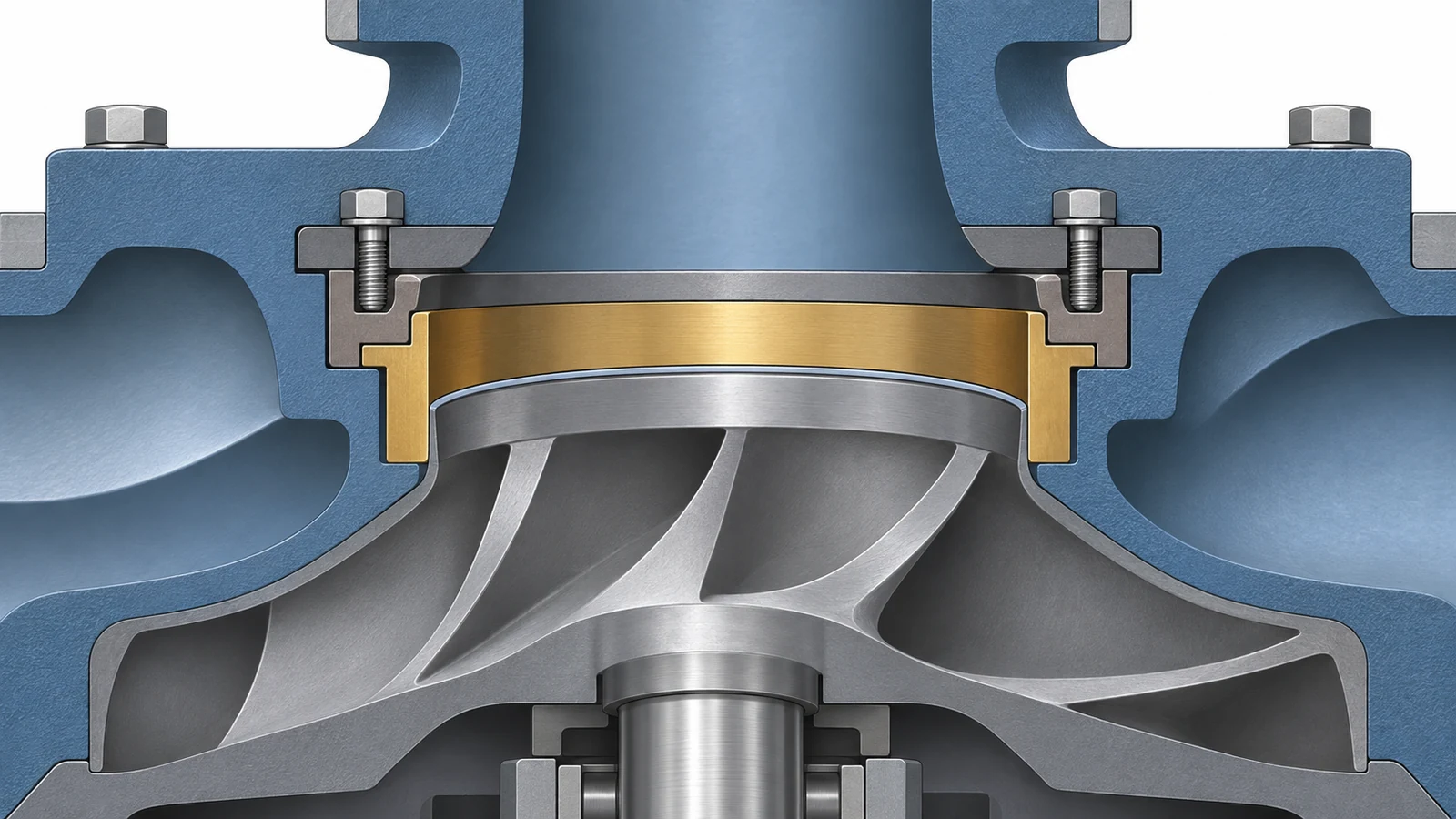
The ring-to-housing or ring-to-impeller seat prevents unwanted movement. Depending on the design, retention may rely on interference, a shoulder, a locking feature or another arrangement. The running clearance is the space between the stationary ring and rotating surface. It controls a leakage path and must avoid contact under the specified operating conditions.
These dimensions interact because changing the seat can change the ring’s final shape. A thin ring may contract or distort when pressed into a housing, so its free-state bore does not automatically equal its installed bore. Relate the running gap to the installed assembly or to a validated manufacturing sequence, not to the loose component alone.
Choose the retention scheme from the seat
Define which component carries the ring, where it locates axially, how it is prevented from moving, and how it can be removed if replacement is intended. A drawing that gives only the ring’s nominal outside diameter may omit seat depth, shoulder, split, key, pin or another retention detail. Material pair, wall thickness, temperature range and service loads can affect the fit and assembly method.
A press fit is not a universal answer. Too little retention can permit movement; excessive interference can distort a thin ring or make installation damage more likely. The designer should specify the fit and installation condition for the exact materials and geometry. General shaft-and-bore fit principles appear in the site’s bore and shaft fit guide, but the pump drawing and OEM limits govern the ring.
Treat running clearance as an assembled condition
Running clearance is affected by the installed ring size, rotating member size, eccentricity, runout, bearing movement, shaft deflection, temperature and fluid conditions. Different materials can expand at different rates. A cold inspection dimension is therefore one input to the operating design. The pump designer determines the acceptable gap for the pump type, duty, materials and speed. For pump wear ring clearance, distinguish this operating gap from the ring-to-seat retention fit and account for the specified assembly and temperature condition.
Be precise about whether the requirement is radial or diametral. For a concentric ring and rotor, diametral clearance is the difference between corresponding diameters; radial clearance describes the gap from one side of the annulus. The terms are not interchangeable. State the convention and measurement location, especially when an OEM table uses a particular definition.
| Requirement | Interface | What it must control |
|---|---|---|
| Retention fit | Ring OD to its seat | Location, assembly, movement and removal |
| Installed ring bore | Ring ID after mounting | Seat-induced distortion and final geometry |
| Operating clearance | Ring to rotating counterface | Leakage path and noncontact operation at design conditions |
Measure without mixing clearance terms
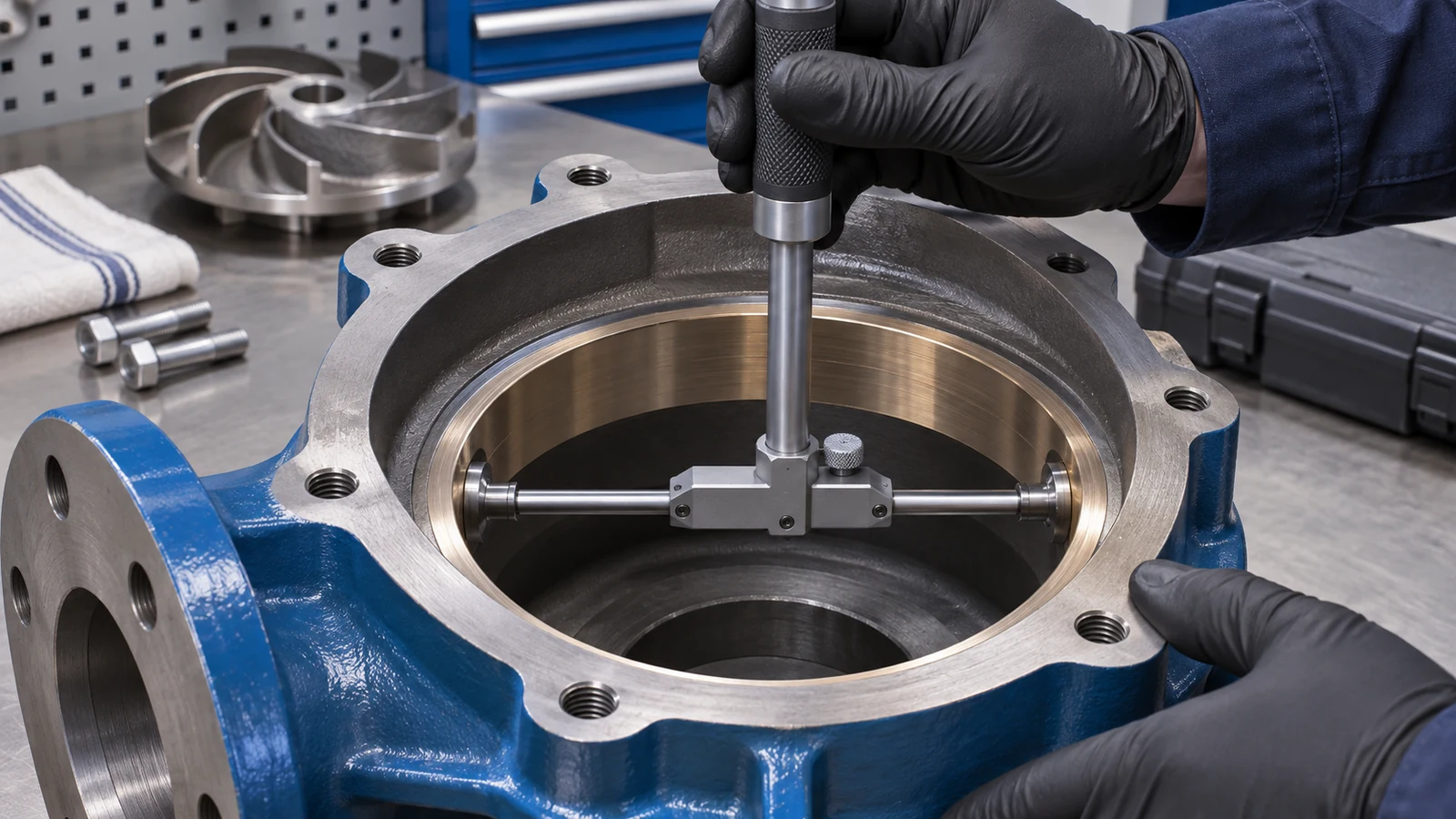
For a loose ring, inspect the specified diameters, form, width and faces using methods suited to its size and geometry. For the assembled gap, measure or calculate from actual mating dimensions and account for eccentricity if the specification requires it. One reading at one angular position may miss a local tight spot; define locations or a functional check when uniformity is part of acceptance.
Inspect the seat and ring separately before assembly, then record the installed condition if the design depends on it. Burrs, raised edges or contamination at a shoulder can tilt the ring and create uneven clearance. If the ring is replaceable, define the seat condition after removal and whether re-machining or replacement is allowed.
Instruments do not establish operating clearance unless assembly state and reference surfaces are controlled. Use the OEM assembly drawing or approved procedure for values. Do not transfer a clearance from another model just because its rings look similar.
Plan machining and replacement around the design
Machining sequence should preserve concentricity between the seat and housing’s functional axis. The running surface may be finished after installation if that is the approved design route; in other cases, the finished ring is mounted without a post-installation cut. Suitability depends on material, wall thickness, retention details, tooling access and OEM procedure.
Replacement changes the inspection question. A worn ring may have a larger running gap while the seat remains serviceable; a loose ring may point to retention or seat damage instead. Diagnose those separately. Adding material, re-machining or changing fit should follow an approved repair plan because altered geometry affects both retention and running clearance.
For related impeller interfaces, the site’s impeller machining page provides component context. It does not replace the pump-specific acceptance drawing.
Write acceptance criteria that separate the fits
A checkable package identifies ring material and revision, housing or impeller seat, retention method, seat dimensions, installed ring condition, clearance convention, measurement temperature and method, inspection locations, and the document that owns allowable values. Include rotor or mating counterface data needed to verify the pair. If runout or bearing movement is part of the clearance budget, name the relevant source and assembly state.
Keep three decisions distinct: whether the ring is retained, whether installed geometry is acceptable, and whether assembled running clearance meets the pump design. This separation improves supplier inspection and service troubleshooting. A machining result can prove specified part dimensions; pump performance and operating qualification remain with the design and test process. A final pump wear ring clearance review should verify the clearance convention, mating dimensions and assembly state against the pump design requirements.