
Packaging change parts repeatability depends on returning each removed component to its intended working position, not merely on matching dimensions to a drawing. Repeatability depends on how the part locates, how clearance and clamping are managed, how wear is recognized, and whether operators install it in a defined orientation. A guide, stop, spacer or bracket can be accurately machined yet still shift between changeovers if the locating scheme relies on loose fasteners or an ambiguous edge. Design the interface around the machine’s functional datums and make acceptance reproduce the installed condition.
Find the source of changeover variation
Observe what moves when the format changes. Is the part removed and replaced, adjusted along a slot, flipped, or exchanged as part of a kit? Identify contact surfaces that stop motion, fasteners that clamp the part, and clearances that permit adjustment. A changeover problem may come from debris on a seat, operator sequence, worn contact faces, inconsistent tightening, or a locating feature that never constrained the required direction.
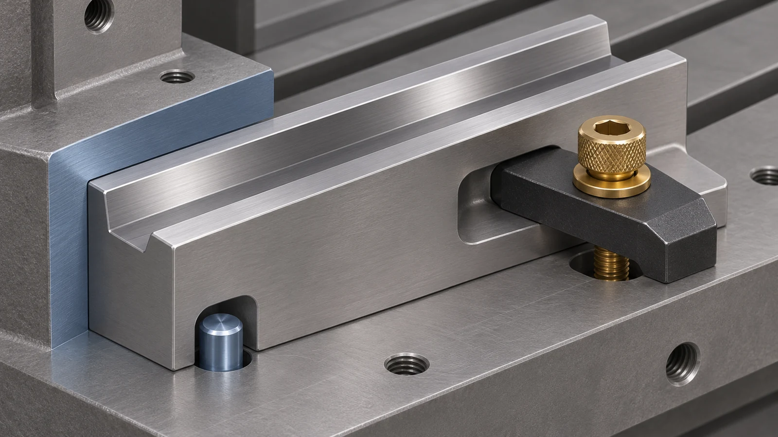
Separate positioning from clamping. A screw can hold a part down while allowing it to slide in-plane. A shoulder, pin, key, rail or matched face may establish position while the fastener supplies clamp force. If one screw is expected to both locate and clamp, define its fit and installation method so the result is repeatable.
Give the part a repeatable locating scheme
Build a datum reference from how the change part contacts the machine. A base face may set height, a stop face may control the product path, and a pin or rail may set lateral position. The functional features depend on whether the component guides a container, supports a product, sets a sensor or establishes a tool position. Use the machine frame and mating part to identify the reference; the largest face is not automatically the functional datum.
For replaceable components, avoid unnecessary overconstraint. Multiple tight pins and a broad face can bind if machine and part vary, while excessive clearance can allow drift. Decide which features locate and which provide clearance, then dimension them accordingly. If adjustment is intentional, define its range and how the final setting is recorded. This locating hierarchy is central to packaging change parts repeatability: constrain the required directions and leave intentional adjustment free.
Spend tolerance where the format depends on it
Prioritize dimensions that control product position, sealing, cut or fill alignment, sensor response or safe clearance. Nonfunctional outer edges may not need the same tolerance. Build a stack from machine datum through mounting interface to working surface to see where variation enters and which component owns each portion. Tightening every dimension without a functional chain can increase cost without improving changeover.
| Interface element | Repeatability risk | Useful definition |
|---|---|---|
| Locating face or shoulder | Debris, burrs, rocking or wear | Contact area, orientation and edge condition as needed |
| Dowel, pin or rail | Clearance, damage or inconsistent engagement | Fit, position, insertion direction and replacement method |
| Clamp fastener | Sliding during tightening or variable preload | Clamp location, sequence and whether torque is controlled |
| Adjustable slot | Unrecorded setup drift | Adjustment range, reference and lock state |
| Working surface | Wear changes product path or clearance | Critical profile, inspection points and replacement limit |
Correct values come from the machine’s functional requirement and mating design. This is a tolerance-allocation framework, not a universal packaging-equipment specification.
Make wear and orientation visible
Parts that are reversed, mixed between formats or installed at a neighboring station can create the same symptom as a dimensional error. Use clear part identification, orientation features or an assembly list where the risk justifies them. If left- and right-hand parts are nearly identical, a physical asymmetry or unmistakable marking can prevent a wrong installation, subject to cleanliness and product-contact needs.
Define which contact surfaces are expected to wear and how the condition is judged. A visual check may suit a noncritical guard, while a guide that controls product path may need a measurable limit or replacement criterion from the machine designer. Do not invent a life interval; wear depends on product, speed, contact, cleaning and operation.
Verify location as the machine uses it
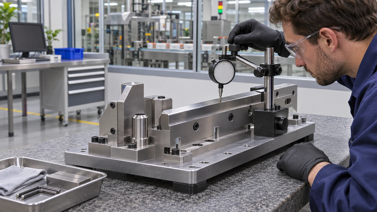
Inspect critical features relative to their locating datums, then check the installed relationship on a representative fixture when the drawing requires it. The fixture must reproduce actual stops, pins, clamp points and orientation. A part measured from arbitrary edges on a surface plate can pass while sitting incorrectly in the machine.
A useful repeatability check removes and reinstalls the component using the documented sequence, then measures the working feature from the machine reference. If operators adjust it during setup, record the setting and reference. Inspection should distinguish part variation from fixture variation and operator method; otherwise the report cannot identify which part of the system needs correction.
The site’s CNC milling page provides machining context. This article does not claim the site supplies packaging machinery or validates an entire production line.
Prepare a change-part drawing and RFQ package
Provide machine maker and model when known, station and format, part identifier and revision, mating interface, working datums, material and finish requirements, critical dimensions, adjustment range, identification needs, quantity and inspection method. CAD helps communicate geometry, but does not replace a released drawing or acceptance definition. If a worn sample is supplied, state whether it is reference only; copying it blindly may reproduce wear instead of intended geometry.
Clarify which items are included in the change-part package and which remain machine-side. If a supplier machines only a bracket or guide, do not assume installation, timing, sensor setup or production validation is included. A clear scope makes repeat orders easier to compare and keeps machining acceptance separate from machine commissioning. For packaging change parts repeatability, record the locating scheme, adjustment range, installation orientation and verification condition in the part package.
The site’s quality page gives general information about its approach; project-specific inspection records should be stated in the RFQ.