
Questa guida segue un passaggio dallo schema all'intersezione forata, alla sbavatura, alla chiusura, alla pulizia e al collaudo. Si applica ai collettori idraulici, pneumatici, del gas, del refrigerante e dei fluidi di processo, mentre i materiali effettivi e i limiti di collaudo restano specifici del progetto.
Tradurre lo schema in geometria solida
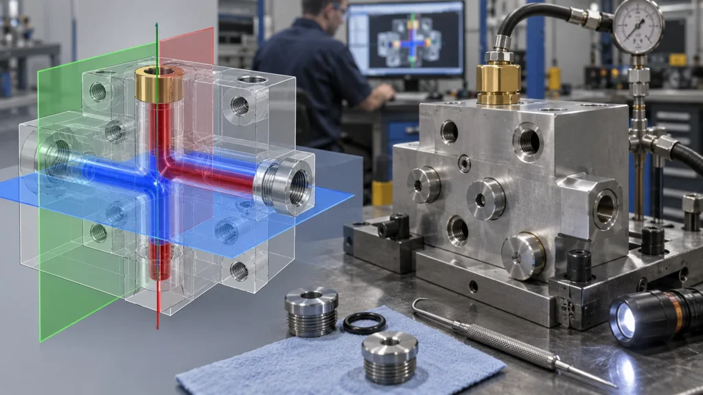
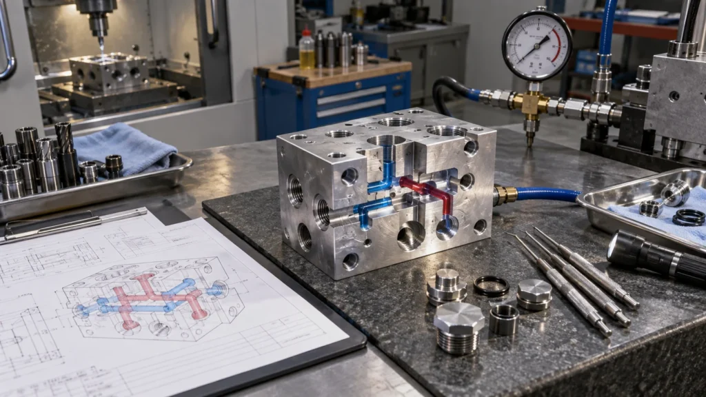
 Creare una mappa circuito-caratteristica che colleghi ogni porta, passaggio forato, cavità per valvola, tappo, restrittore, sensore e interfaccia di montaggio allo schema del fluido. Verificare che i passaggi si colleghino solo dove previsto e che le punte delle punte, le profondità delle filettature e i tappi non ostruiscano un altro circuito.
Utilizzare viste in sezione o revisione CAD trasparente per la geometria nascosta. Identificare entrata e uscita della punta, accesso per la sbavatura, accesso per l'ispezione, flusso di pulizia e metodo di chiusura. Una modifica del percorso che fa risparmiare un'attrezzatura può creare una bava inaccessibile o una parete debole.
Creare una mappa circuito-caratteristica che colleghi ogni porta, passaggio forato, cavità per valvola, tappo, restrittore, sensore e interfaccia di montaggio allo schema del fluido. Verificare che i passaggi si colleghino solo dove previsto e che le punte delle punte, le profondità delle filettature e i tappi non ostruiscano un altro circuito.
Utilizzare viste in sezione o revisione CAD trasparente per la geometria nascosta. Identificare entrata e uscita della punta, accesso per la sbavatura, accesso per l'ispezione, flusso di pulizia e metodo di chiusura. Una modifica del percorso che fa risparmiare un'attrezzatura può creare una bava inaccessibile o una parete debole.
Cross-Hole Intersections Create Hidden Risk
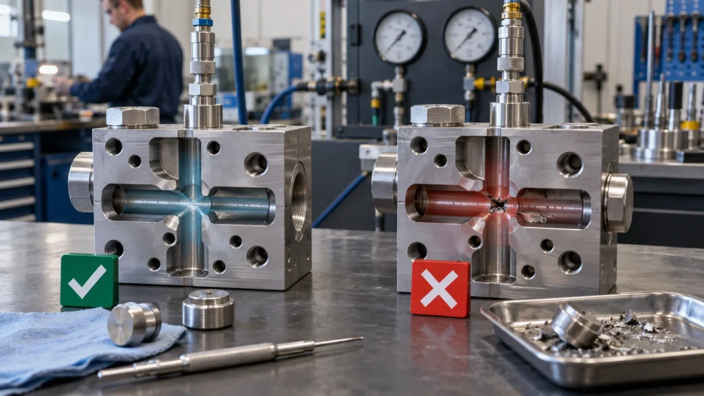
When a drill breaks into another passage, it can form a burr, cap, or sharp edge that is difficult to reach. Tool condition, feed, drill geometry, material, angle, and intersection location affect the result. Plan the drilling sequence and deburring method before machining.
Possible methods include mechanical access, specialized cross-hole tools, abrasive flow, thermal or electrochemical processes, and controlled manual work, but suitability depends on material, size, cleanliness, and edge requirement. The drawing should define functional edge condition where loose material or flow disturbance matters.
Inspection may require borescopes, controlled flushing, sectioned validation samples, flow checks, or process qualification. Visual access from an opening is not proof of every internal intersection.
Datums Must Serve Ports and Mounting
 Port position often matters relative to mounting faces, valve cavities, connectors, and external plumbing. Establish a functional datum system that represents installation. Group related cavities and sealing faces in setups that preserve position and orientation.
Deep drilling can wander, and intersecting holes can amplify positional error. Review diameter-to-depth ratio, drill guidance, breakthrough condition, and remaining wall. If a passage position is more important than an external dimension, the drawing should communicate that relationship.
Port position often matters relative to mounting faces, valve cavities, connectors, and external plumbing. Establish a functional datum system that represents installation. Group related cavities and sealing faces in setups that preserve position and orientation.
Deep drilling can wander, and intersecting holes can amplify positional error. Review diameter-to-depth ratio, drill guidance, breakthrough condition, and remaining wall. If a passage position is more important than an external dimension, the drawing should communicate that relationship.
Sealing Features Need Protected Process Zones
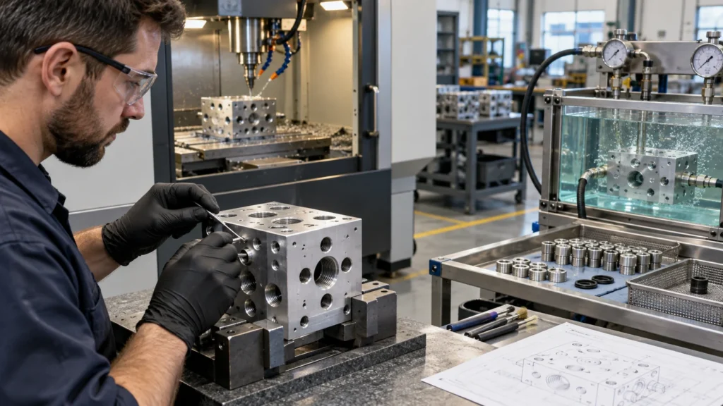 O-ring grooves, face seals, tapered or straight threads, valve seats, counterbores, and plug bores depend on geometry, texture, edge condition, and cleanliness. Mark sealing zones and protect them from chuck marks, blending, blasting, scratches, and coating buildup.
Material Follows Fluid and Pressure Duty
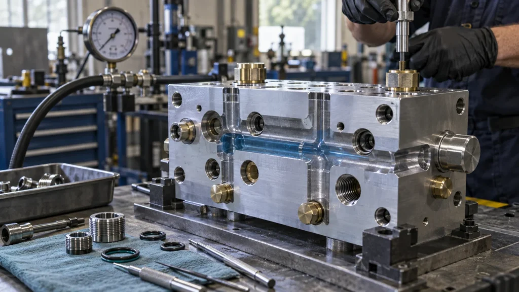 Aluminum, stainless steel, brass, engineering plastics, and other materials offer different corrosion, mass, strength, temperature, wear, and cleanliness behavior. Selection depends on fluid compatibility, pressure, environment, joining, finish, thread durability, and regulations.
Surface treatment can improve corrosion or wear but may affect threads, seals, conductivity, and cleanliness. Mask or finish-machine selected interfaces as needed. For plastic manifolds, creep, moisture, thermal expansion, and thread strategy deserve specific review.
Aluminum, stainless steel, brass, engineering plastics, and other materials offer different corrosion, mass, strength, temperature, wear, and cleanliness behavior. Selection depends on fluid compatibility, pressure, environment, joining, finish, thread durability, and regulations.
Surface treatment can improve corrosion or wear but may affect threads, seals, conductivity, and cleanliness. Mask or finish-machine selected interfaces as needed. For plastic manifolds, creep, moisture, thermal expansion, and thread strategy deserve specific review.
Cleanliness Must Be Verifiable
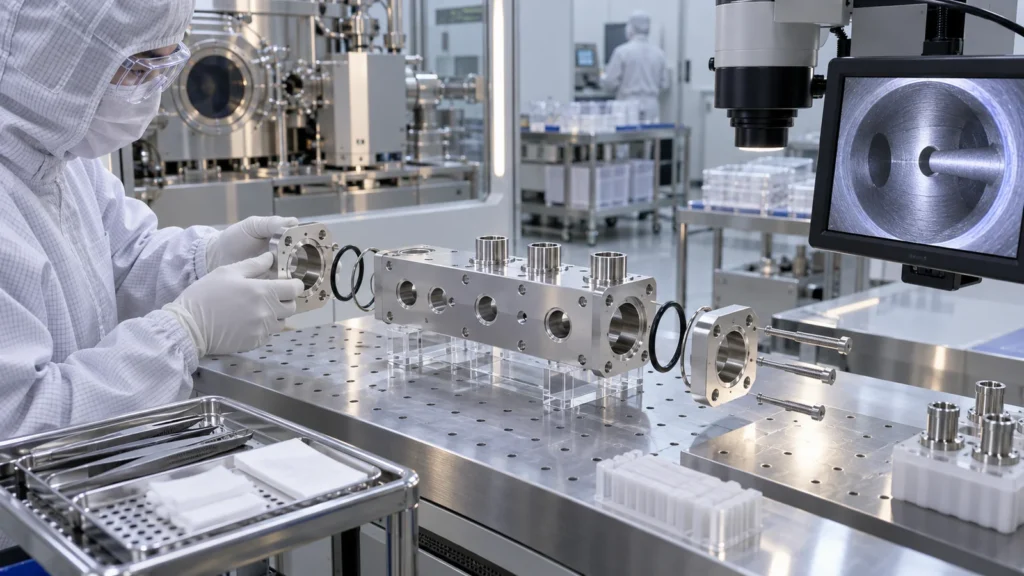 Define acceptable particles or residue, cleaning chemistry, flush direction, drying, inspection, and packaging. Hidden dead legs and blind passages can retain chips or liquid. Temporary plugs and shipping caps should prevent recontamination without shedding material.
Cleaning cannot replace upstream burr control. Verify difficult intersections before closure, and protect the cleaned state during leak testing and handling. The quality plan should link lot identity, cleaning status, and test records.
Define acceptable particles or residue, cleaning chemistry, flush direction, drying, inspection, and packaging. Hidden dead legs and blind passages can retain chips or liquid. Temporary plugs and shipping caps should prevent recontamination without shedding material.
Cleaning cannot replace upstream burr control. Verify difficult intersections before closure, and protect the cleaned state during leak testing and handling. The quality plan should link lot identity, cleaning status, and test records.
Build a Test Matrix, Not One Generic Leak Test
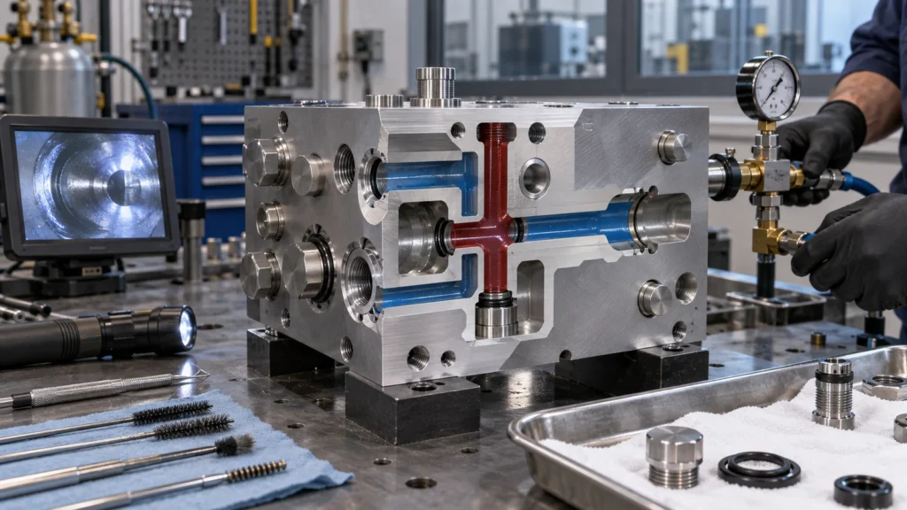
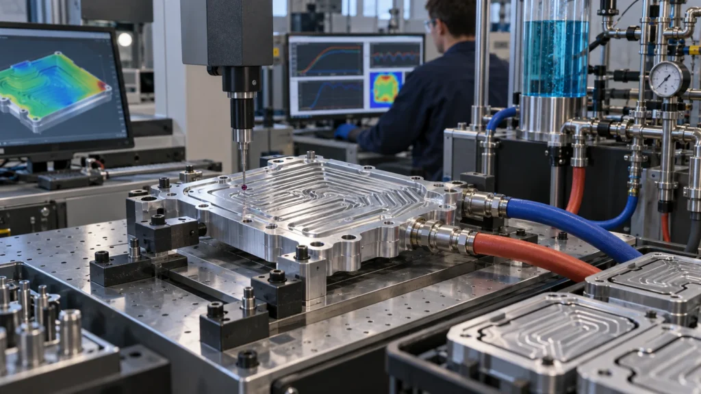 Different tests answer different questions. Proof testing checks structural integrity under a defined condition. External leak testing checks boundary leakage. Circuit-isolation testing checks unintended internal communication. Flow or pressure-drop testing checks passage behavior. Functional valve testing checks assembled performance.
Specify medium, pressure, temperature, stabilization, duration, connection, allowable leakage or pressure change, and safety controls as required by the program. Confirm whether testing occurs before or after finish, plugs, valves, or cleaning. Do not copy a test value from another manifold.
Different tests answer different questions. Proof testing checks structural integrity under a defined condition. External leak testing checks boundary leakage. Circuit-isolation testing checks unintended internal communication. Flow or pressure-drop testing checks passage behavior. Functional valve testing checks assembled performance.
Specify medium, pressure, temperature, stabilization, duration, connection, allowable leakage or pressure change, and safety controls as required by the program. Confirm whether testing occurs before or after finish, plugs, valves, or cleaning. Do not copy a test value from another manifold.
Manifold RFQ Checklist
This failure-focused plan expands the parent applicazioni della lavorazione CNC article for fluid-control hardware.
Manifold Machining FAQs
No. Flushing can remove loose debris but may not remove attached burrs. Prevent, deburr, and verify intersections through a qualified process.
Should all manifold passages be pressure tested together?
Not always. Testing together may miss internal cross-leakage. The matrix should isolate circuits where unintended communication is a risk.
Can anodizing cover internal passages?
Coverage and effect depend on process access, chemistry, geometry, and specification. Confirm internal treatment, masking, rinsing, and dimensional impact with the finisher.