
This guide begins with alignment stability rather than machine capability. It shows how to allocate adjustment, select interfaces, control stress, and verify an optomechanical component without pretending the machined mount is the optical system.
Start With an Alignment Budget
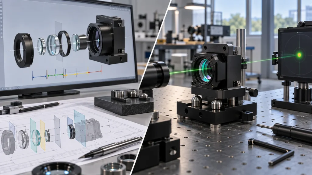 Divide allowable optical error among optic manufacturing, mount geometry, adjustment range, assembly, temperature, vibration, and long-term stability. This prevents one machined diameter from receiving an unrealistic share of the system requirement.
Decide what is fixed and what is adjustable. A precision bore may center an optic, while axial focus is set by a shoulder, spacer, thread, or shim. Kinematic or flexure elements may control position without over-constraining the optic. Adjustment should have enough range to absorb expected variation but enough resolution and locking stability for service.
Divide allowable optical error among optic manufacturing, mount geometry, adjustment range, assembly, temperature, vibration, and long-term stability. This prevents one machined diameter from receiving an unrealistic share of the system requirement.
Decide what is fixed and what is adjustable. A precision bore may center an optic, while axial focus is set by a shoulder, spacer, thread, or shim. Kinematic or flexure elements may control position without over-constraining the optic. Adjustment should have enough range to absorb expected variation but enough resolution and locking stability for service.
Constraint Without Optical Stress
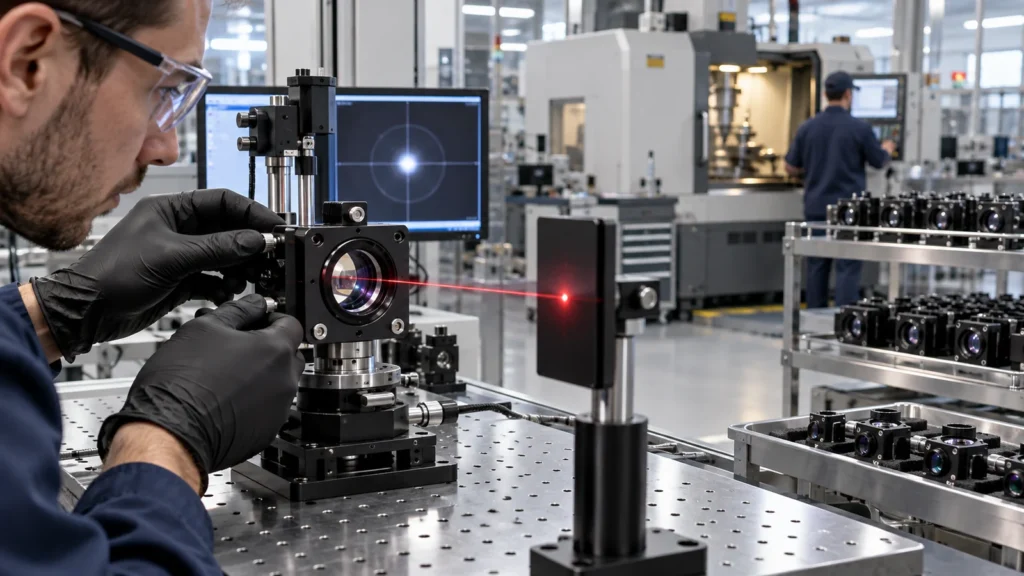 Clamping an optic too tightly can deform it or create stress that changes performance. Too little retention can allow shift under vibration or temperature. The mount must locate the optic, provide controlled preload, accommodate material expansion, and avoid point loads on vulnerable edges.
Threads, retaining rings, adhesives, flexures, pads, and spring elements each create different assembly behavior. Define contact geometry and torque or preload strategy. Avoid using a tight machined fit as the only solution when the optic and housing expand differently.
Clamping an optic too tightly can deform it or create stress that changes performance. Too little retention can allow shift under vibration or temperature. The mount must locate the optic, provide controlled preload, accommodate material expansion, and avoid point loads on vulnerable edges.
Threads, retaining rings, adhesives, flexures, pads, and spring elements each create different assembly behavior. Define contact geometry and torque or preload strategy. Avoid using a tight machined fit as the only solution when the optic and housing expand differently.
Connect Mechanical Datums to the Optical Axis
The drawing should show which face, bore, cone, or hole pattern locates the mount in the instrument and which features locate the optic. If those groups are machined in unrelated setups, tolerance stack and datum recovery can shift alignment.
Use geometric controls that describe functional relationships: axis to mounting face, optic seat to reference bore, hole pattern to optical center, or mirror plane to kinematic contacts. Keep critical features in a common setup when feasible, but verify that workholding does not distort thin rings or flexures.
The optical housing machining page supports related commercial requirements; this guide focuses on alignment logic.
Thermal Stability Starts With Material Pairs
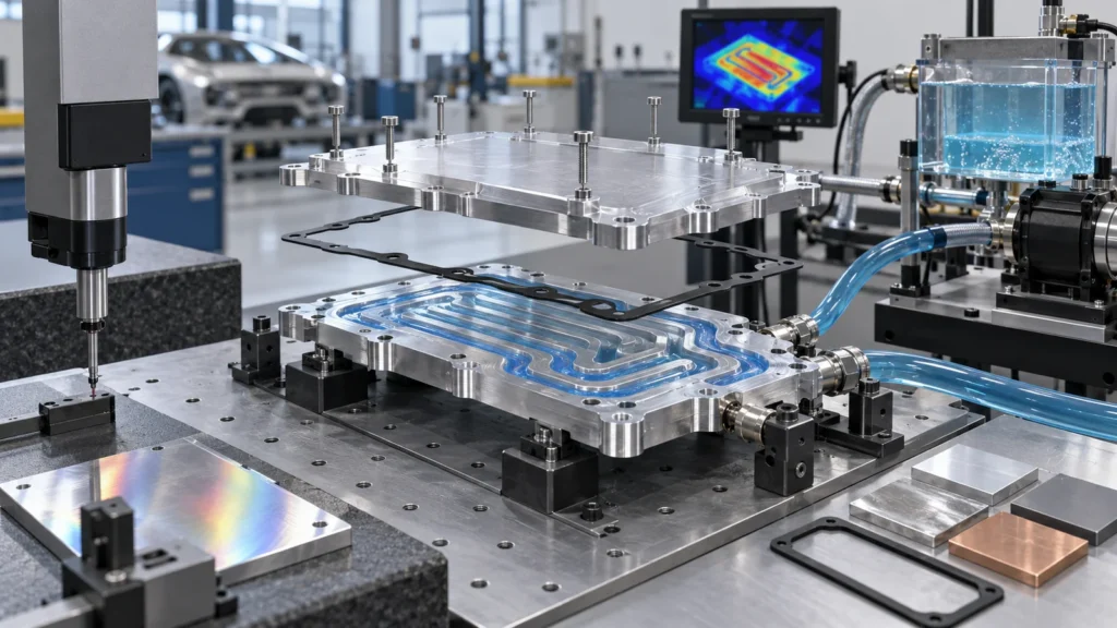 Aluminum, stainless steel, titanium, low-expansion alloys, polymers, glass, and adhesives expand differently. A mount that aligns at room temperature can shift focus, tilt an optic, or increase clamp stress across the operating range. Consider the complete stack, not the mount alone.
Material choice balances expansion, stiffness, mass, conductivity, machinability, corrosion, magnetic behavior, and cost. A lower-expansion material is not automatically best if it adds mass, thermal gradients, or incompatible contacts. Athermal design may use geometry and compliant constraint as well as material.
Aluminum, stainless steel, titanium, low-expansion alloys, polymers, glass, and adhesives expand differently. A mount that aligns at room temperature can shift focus, tilt an optic, or increase clamp stress across the operating range. Consider the complete stack, not the mount alone.
Material choice balances expansion, stiffness, mass, conductivity, machinability, corrosion, magnetic behavior, and cost. A lower-expansion material is not automatically best if it adds mass, thermal gradients, or incompatible contacts. Athermal design may use geometry and compliant constraint as well as material.
Machining and Finishing Can Move the Mount
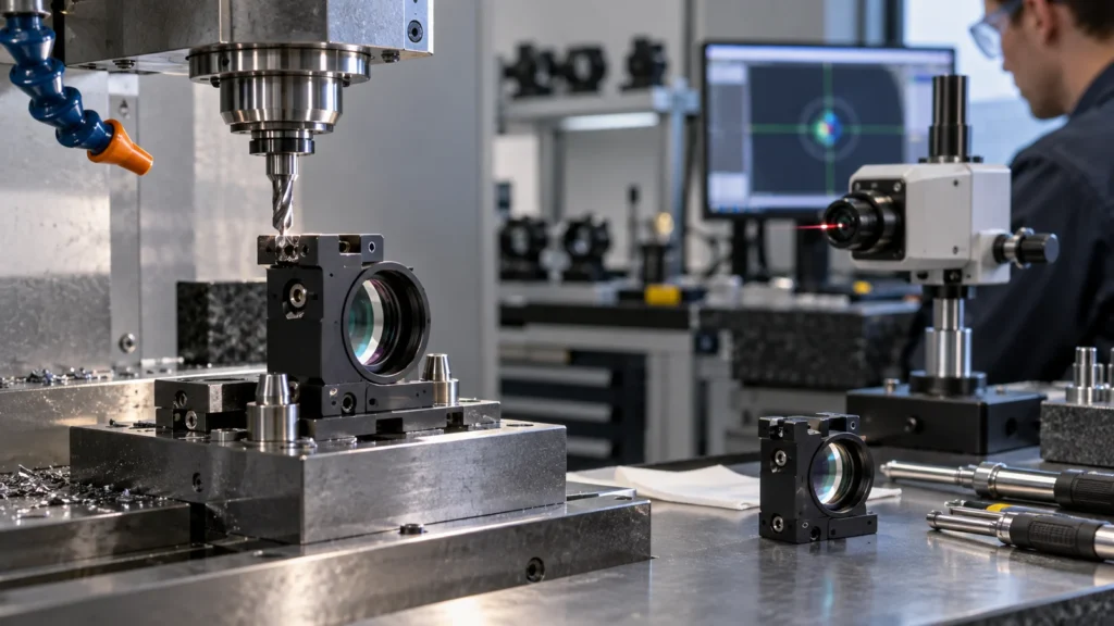 Thin rings, split clamps, flexures, and heavily pocketed bases can relax after material removal or change shape under workholding. Plan balanced roughing, stable stock, controlled clamping, and final passes after the part has settled. Measure in the specified free or constrained state.
Heat treatment, anodizing, plating, blasting, or blackening can alter surfaces and release stress. Inspect critical geometry at the state that enters assembly. Protect optical seats from handling damage and finish buildup.
Thin rings, split clamps, flexures, and heavily pocketed bases can relax after material removal or change shape under workholding. Plan balanced roughing, stable stock, controlled clamping, and final passes after the part has settled. Measure in the specified free or constrained state.
Heat treatment, anodizing, plating, blasting, or blackening can alter surfaces and release stress. Inspect critical geometry at the state that enters assembly. Protect optical seats from handling damage and finish buildup.
Black Surfaces, Masks, and Stray Light
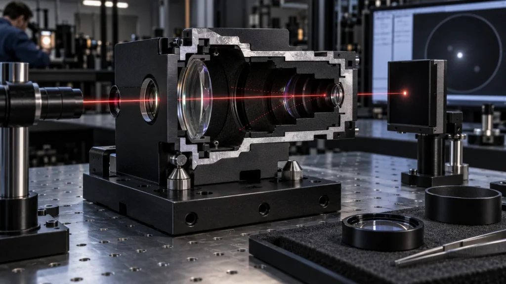 A black appearance does not fully define optical performance. Surface texture, coating type, wavelength, viewing angle, cleanliness, and internal geometry affect reflection and stray light. Specify the approved finish and zones instead of requesting generic “matte black.”
Mask bearing fits, threads, grounding contacts, precision seats, or adhesive areas as required. Finish thickness can change retaining-ring behavior and optic centering. Review the surface-finish options with optical, mechanical, and environmental needs.
A black appearance does not fully define optical performance. Surface texture, coating type, wavelength, viewing angle, cleanliness, and internal geometry affect reflection and stray light. Specify the approved finish and zones instead of requesting generic “matte black.”
Mask bearing fits, threads, grounding contacts, precision seats, or adhesive areas as required. Finish thickness can change retaining-ring behavior and optic centering. Review the surface-finish options with optical, mechanical, and environmental needs.
Mechanical Metrology and Optical Verification Answer Different Questions
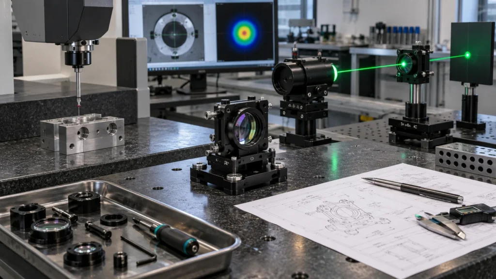 CMM, bore, height, roundness, and surface measurements can verify the mechanical drawing. They do not necessarily prove wavefront, beam position, focus, or assembled stability. The verification plan should connect mechanical results to an optical alignment or functional test where system performance requires it.
Optomechanical RFQ Checklist
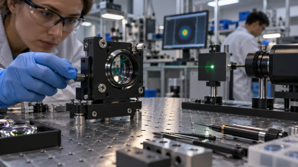
This is the optical-system extension of the parent CNC machining applications topic.
Optical-Mount FAQs
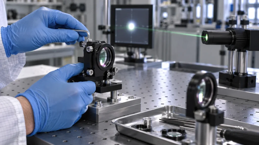
Not automatically. Clearance, centering method, preload, thermal expansion, and edge sensitivity must be considered. A tight fit can stress the optic.
Can black anodizing be used on every optical mount?
Suitability depends on alloy, wavelength, vacuum or cleanliness needs, wear, masking, and appearance. Specify system requirements rather than only color.
Does CMM inspection prove optical alignment?
It proves defined mechanical geometry. Optical alignment also depends on the optic, assembly, preload, adjustment, and environment, so a system-level test may be needed.