
A cutter can look centered and still remove material unevenly. The cause may be runout at the cutting edge, but a visible finish problem can also come from a damaged flute, inconsistent stock, tool deflection, or workholding. The useful question is not only whether the tool spins true; it is where the error enters the tool–holder–spindle assembly and how that error changes under load.
What runout means at the cutting edge
Runout describes the amount a rotating tool or reference surface deviates from its intended axis. Radial runout moves the tool sideways as it rotates; axial runout describes variation along the axis, often noticed as unequal engagement among end-mill teeth. A spindle nose measurement alone does not tell the whole story because each interface and the tool itself can add error.
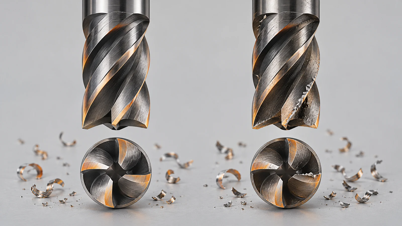
In milling, radial runout can make one flute carry more of the chip load than its neighbors. That flute may wear faster, leave a different surface trace, or produce a size that changes with tool condition. Axial variation can cause one end-cutting edge to cut deeper than another. Neither symptom is unique to runout, so treat it as a testable cause rather than a diagnosis based only on appearance.
Where the error can enter the setup
Think of the rotating assembly as a chain: spindle, taper or interface, toolholder, collet or retention system, and cutter. Dirt, burrs, wear, poor seating, an unsuitable holder, or a damaged tool can disrupt alignment at different points. Long tool stickout and cutting force add deflection, which is not the same as static runout but can look similar once the tool is cutting.
Before changing offsets or replacing a machine component, isolate the setup. Clean mating surfaces using the approved shop method, inspect the cutter and holder, reseat the tool, and compare readings at more than one position. For a broader view of the operation, see the site’s CNC milling capability and the parent guide to the CNC machining process.
Match the symptom to a likely cause
| Observed symptom | Possible runout-related mechanism | Other causes to rule out |
|---|---|---|
| One flute shows noticeably more wear | Unequal radial chip load | Uneven edge geometry, material interruption, chip packing |
| Finish changes around a bore or pocket | Tool center shifts through rotation | Deflection, stock variation, chatter, changing engagement |
| End-milled floor has a step or uneven witness | Axial edge-height difference | Tool length setting, machine tram, interpolation or setup error |
| Reading changes after a tool change | Seating, collet, or holder interface variation | Different cutter geometry or measurement setup |
This is a fault-isolation aid, not a one-to-one diagnostic chart. Record the tool, holder, measurement location, and cutting condition so comparisons remain meaningful.
Measure near the working end
Use a clean, suitable indicator and a repeatable setup. Measure on a straight, accessible shank or gauge surface close to the cutting end, then rotate the assembly by hand as appropriate for the machine’s safety procedure. A measurement farther from the cutter may miss angular error that grows with distance. Avoid pushing the indicator hard enough to deflect a small tool.

Check the result at the same location after reseating the tool. If the reading follows the cutter when it is moved to another holder, inspect or replace the cutter. If it follows the holder, examine the collet and interface. If it persists across assemblies, involve the person responsible for spindle inspection. Acceptance limits should come from the machine, holder, tool, process, and drawing requirements—not a generic number detached from the application.
Reduce runout-related variation before it reaches the part
- Keep holder tapers, collets, and cutter shanks clean and protected.
- Use a holder and tool combination suited to the cutter diameter, stickout, and operation.
- Replace damaged or worn consumables rather than compensating blindly with offsets.
- Verify tool condition when a finish, size, or tool-life pattern changes unexpectedly.
- For critical features, define the measurement method and acceptance criteria in the process plan.
When a part’s acceptance depends on dimensional evidence, connect tool checks to the inspection plan rather than treating them as an isolated maintenance task. The site’s quality overview describes the quality context; actual inspection requirements still need to be agreed for the part and drawing.
Questions machinists and buyers ask
Can a low runout reading guarantee a good finish?
No. It removes one possible source of uneven cutting, but tool geometry, rigidity, speed and feed, material behavior, coolant, and workholding also affect the result.
Should runout be measured at the spindle or the cutter?
Both locations can help isolate a source. For the part-making effect, a repeatable measurement near the working end is more informative than relying only on a spindle reference.
Is tool deflection the same as runout?
No. Runout is geometric variation during rotation; deflection is displacement under force. Cutting can combine both, so compare a static measurement with behavior under the actual operation.