
A sculpture model or display prototype starts with a visual goal, but it still has to fit available stock, leave room for tools, and hold together after machining. First decide what the model must communicate: overall form, surface appearance, an assembly interface, or a product concept viewed at a particular scale. That answer determines which faces need finish control, where the model can be split, and whether machined metal or plastic components are a sensible route. This guide translates a sculptural form into machinable parts; it does not promise full-service sculpture carving, painting, or large-format model making. For sculpture models, define which forms and surfaces must read clearly at viewing distance, then test those priorities against stock, tool access, and assembly limits.
Decide what the model needs to communicate
For sculpture models built from CNC-machined components, distinguish what the viewer needs to see from what the part must physically do. A model may communicate silhouette, proportion, color blocking, or the relationship between a visible shell and its support without being powered or loaded. A functional prototype, by contrast, is intended to test fit, motion, heat, strength, or another operating condition. One sample can serve both purposes only if its materials, interfaces, and acceptance criteria support both roles.
Write down the viewing distance, expected handling and intended display environment. A small tabletop sample viewed at close range exposes tool marks and seam lines that a large exhibit viewed from several feet away may not. Repeated handling can make a delicate fin, thin wall or sharp edge unsuitable even if it looks correct in CAD. If the model only needs to show form, identify which dimensions are visual references and which interfaces must actually assemble.
Turn the sculpted form into accessible geometry
Organic surfaces can be represented by a dense CAD model, but not every sculpted feature is equally machinable from a solid block. Tool diameter, reach, cutting direction, holder clearance, workholding and the number of accessible sides constrain the final surface. Deep concavities, narrow channels and undercuts may require a different orientation, a smaller tool, multiple setups or a redesigned surface. A five-axis route can reach more orientations, yet it does not eliminate tool-access limits or guarantee that every point can be finished in one setup.
Review the model with the actual stock and datum plan in mind. A narrow projection may need temporary support or a separate component. A deep pocket may trap a tool or leave a radius that changes the intended visual line. Where the surface is primarily visual, a small geometric adjustment can preserve the perceived shape while making cutter access and finishing practical. Mark whether the CAD surface is nominal or whether selected details may be simplified after review. For CNC display model design, identify tool access and support risks before committing to a one-piece form; a planned split can preserve visible geometry while making machining practical.
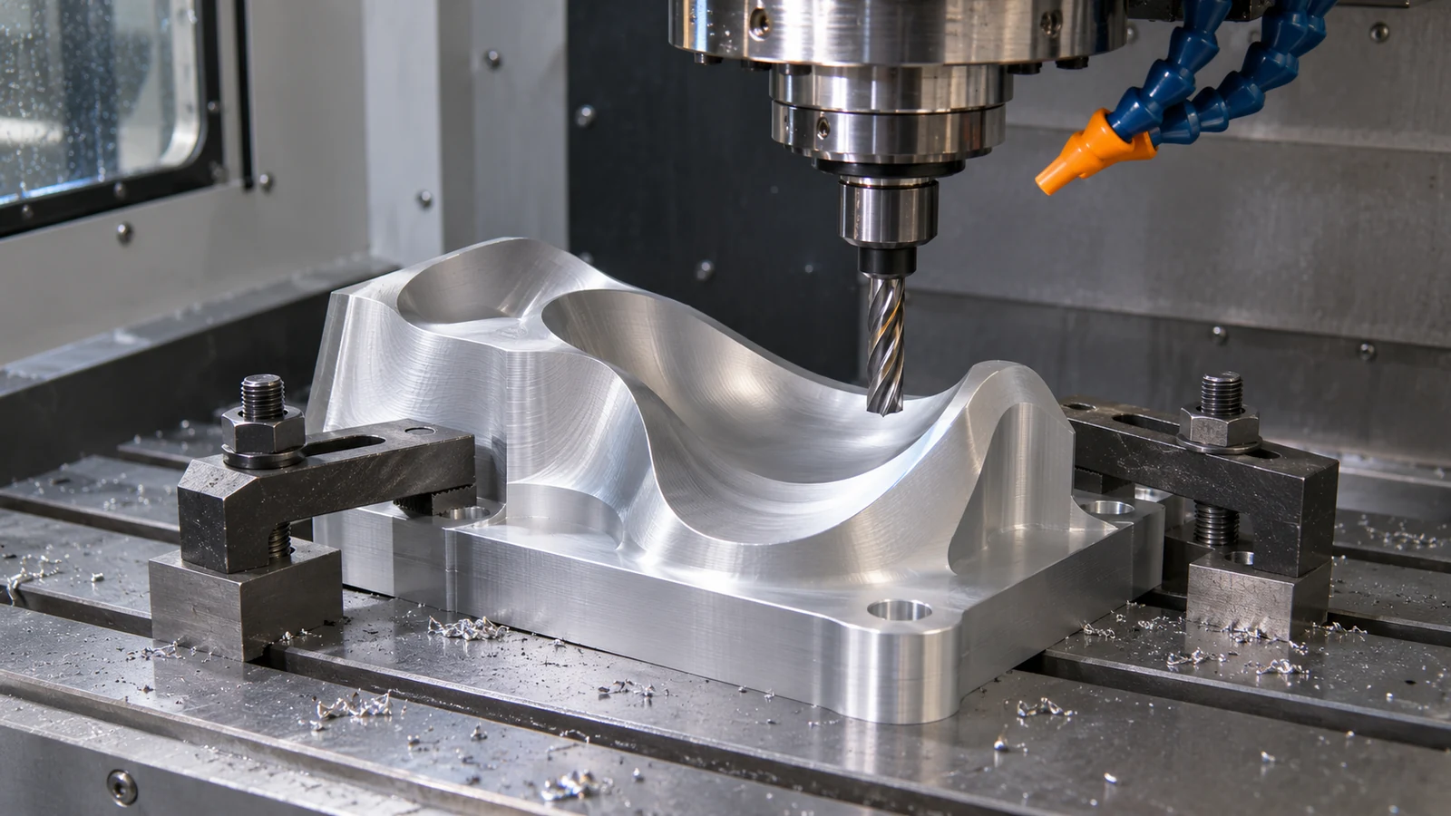
For the machining process itself, the site’s Возможности фрезерования с ЧПУ page describes the available process categories. The suitable axis strategy is determined by the part geometry and project review, not by the word “sculpture.”
Place seams before the toolpath is planned
Large or intricate forms may need to be divided into machined sections because of stock size, tool access, material waste or the need to present multiple faces. The split should follow a natural visual boundary where possible: a base line, panel break, underside, or transition hidden from the principal view. An arbitrary split across a smooth, highly visible surface can create a gap or step that dominates the finished model.
Define how the sections locate and attach. Dowels, shoulders, screws or a base plate can control alignment, but each adds geometry and assembly requirements. A simple fastener may hold pieces together without locating them precisely; a locating feature should have a clear datum relationship and inspection plan. If adhesive or another joining method is used outside the machining scope, identify who owns that operation and how the assembled surface will be accepted.
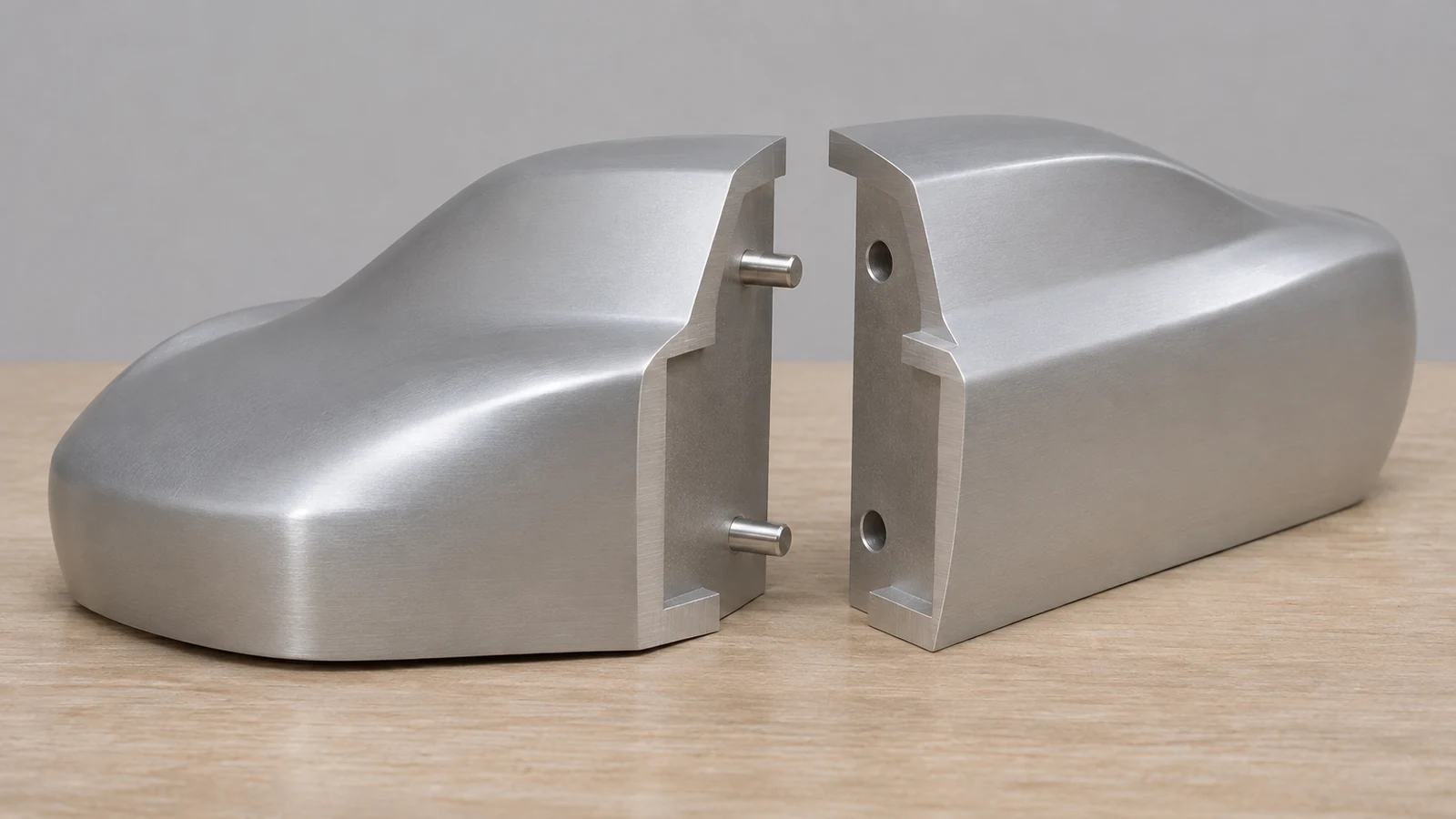
Think about fixture marks and clamping access at the same time. A face needed for workholding may later become visible, so the design may need a sacrificial tab, a hidden fixture pad or a separate base. These choices affect stock utilization and setups. They should be resolved in the model instead of being left to remove material from a cosmetic surface at the end.
Choose material for viewing and handling
Material selection depends on what the display sample must show. Алюминий can suit a light, rigid machined form; steel or stainless steel may be considered when mass, wear or corrosion behavior matters; engineering plastics can support a lighter visual model or an interface sample. These are starting points, not blanket recommendations. The exact grade, stock form, finish and display conditions must be reviewed for the part.
Color and reflectivity can change how a sculpted surface reads. A bright finish emphasizes tool marks and small waviness; a matte finish may soften them but can change edge definition. If a coating, anodizing or polishing operation follows machining, identify the appearance reference, masked surfaces and dimensions that must remain controlled afterward. A display finish does not by itself establish suitability for a functional load or environment.
Compare material mass against how the model will be mounted and handled. A heavy one-piece body may need a substantial base, while a lighter assembled model may need stronger joints. If weight is only an appearance cue, say so; if the sample must represent a production part’s mass or balance, specify that test requirement separately.
Treat visible surfaces as a separate requirement
“Cosmetic finish” is too vague for a supplier to quote or inspect consistently. Mark the primary viewing direction and divide the model into visible, secondary and hidden zones. State the required texture or approved sample for the visible surfaces, define whether toolpath marks are acceptable, and show where edge breaks or polishing may alter the silhouette. A broad finish note across every face can raise cost without improving the display.
Small radii and sharp transitions deserve particular attention. A ball-end cutter leaves a scallop pattern on a contoured face; changing step-over, tool size or finishing direction can alter the visual texture and machining time. A tight inside corner may remain radiused because a rotating cutter has a finite diameter. If a sharp internal line is essential to the appearance, consider whether the geometry can be split, whether a secondary operation is justified, or whether the model can accept a deliberate radius.
After machining, handling, deburring and any finishing operation can affect the surfaces that viewers notice first. A simple protective plan—identify contact areas, packaging orientation and acceptable marks—helps prevent a good machined face from being scratched before display. See the site’s CNC surface-finish options for the process scope; confirm the finish and acceptance reference for the particular model.
Prepare a model package a machine shop can review
Send the native or neutral CAD file, a controlled drawing, units, revision, overall envelope, quantity, material and condition, finish zones, assembly views and the intended display purpose. Mark interfaces that must fit, visible faces that govern appearance, and features that can be treated as reference. Include a view showing the preferred display orientation and note any hidden fixture or mounting surfaces.
For a sculpture project that uses CNC-machined metal or plastic parts, identify the assembly sequence, locating method, and acceptable gaps or steps. State whether the supplier is machining components only or also quoting assembly or outside finishing. Do not assume a CNC part supplier also provides digital sculpting, scanning, foam carving, paint matching, exhibit construction, or complete art installation; confirm those services separately when needed.
Before release, compare the finished model against its purpose. A visual mockup needs controlled form, appearance and display stability; a functional prototype needs the relevant interfaces, material state and test criteria. If one part must satisfy both, list both sets of requirements and identify which characteristics are acceptance-critical. The site’s rapid CNC prototyping workflow covers the broader RFQ-to-test process; this article stays with the appearance-driven decisions that process does not resolve by itself. That separation lets the machining route answer the right question without over-controlling every decorative detail. A final CNC display model design review should compare the machined form, surface zones, assembly and display stability with the model’s intended presentation purpose.