
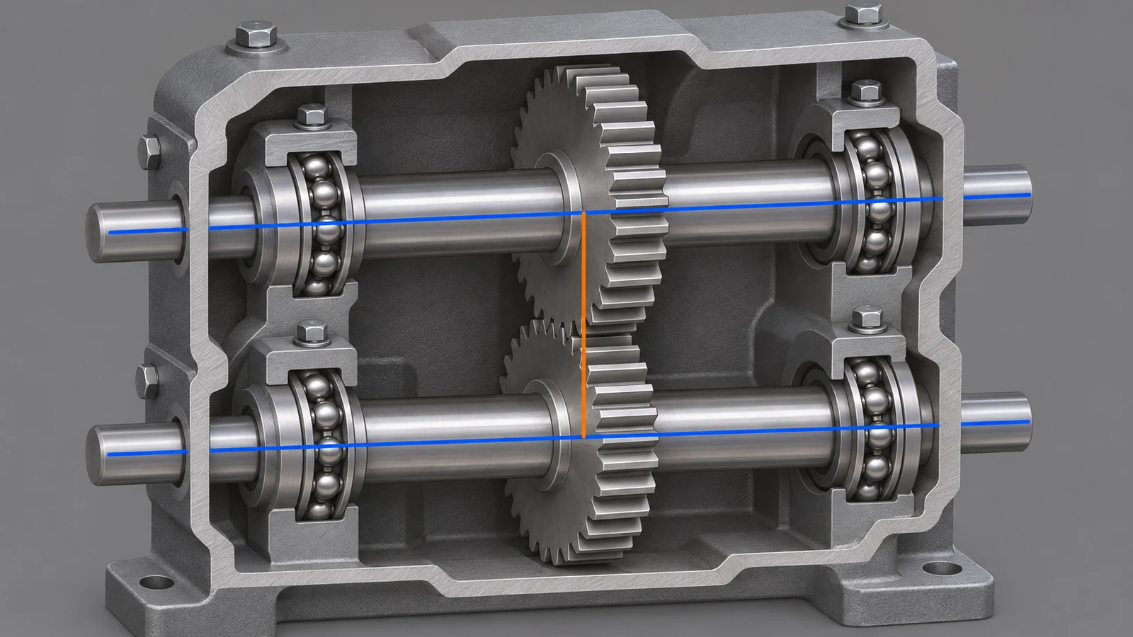
Gearbox housing center distance is established by the relationship between the rotational axes of mating gears, and the housing’s bearing bores help locate those axes. Correct tooth geometry cannot compensate for a housing that places the shafts too close, too far apart, or out of parallel. To make the mesh repeatable, define the functional bore axes from a stable datum scheme, preserve their relationship through machining and assembly, and inspect the housing in the condition that represents its use. The acceptable distance and alignment come from the gear design and assembly requirements; they should not be guessed from a generic machining tolerance.
Start with the gear pair, not the housing alone
The gear designer establishes the required operating geometry from the selected tooth form, module or diametral pitch, tooth counts, profile modifications, load, backlash objective and operating conditions. The housing drawing then translates that design intent into locations for shafts, bearings, shoulders and mounting interfaces. A bore-to-bore dimension is useful only when it identifies which bore axes matter and how the measurement relates to the assembled gear pair.
Do not use nominal center distance as a substitute for a complete gear specification. Shaft deflection, bearing internal clearance, fits, thermal growth and case support can affect the running mesh. These are system inputs for the designer. The machining drawing should control the housing features needed to realize the design, without implying that machining alone validates gear performance.
Make the bearing axes the locating backbone
Choose datums that reflect how the case locates in the gearbox assembly. A mounting face may establish the axial plane; one bearing bore or a set of coaxial bores may establish an axis; a dowel, side face or other feature can control clocking. The exact scheme depends on the case and assembly. Convenient outside surfaces should not become primary references if they do not locate the bearings or close the housing in service.
For separate bearing seats, define the axes’ relationship directly. That may involve center distance, parallelism, orientation to the mounting datum and the position of each bore. Avoid a chain of unrelated dimensions whose accumulated variation obscures the allowed relationship. Coordinate geometric controls with the gear and bearing requirements. For a gearbox housing center distance check, evaluate the defined bearing-bore axes against the functional datums and control parallelism separately.
Страница сайта обработка деталей трансмиссии page describes related component scope. This article addresses geometry handoff, not gear-design calculation or a guaranteed mesh result.
Keep split housings from moving the relationship
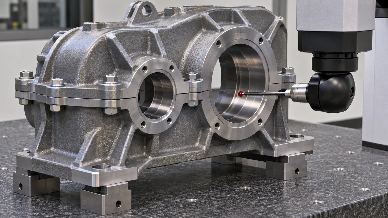
A split case adds an interface that can affect bore position and axis alignment. If bearing bores are finished across joined halves, the specified fasteners, dowels, joint faces, tightening sequence and clamping condition become part of the measurement definition. A free-state half-shell may not represent geometry after assembly. State whether inspection is performed on a component or bolted assembly, and define the hardware and condition when they affect acceptance.
Joint-face burrs, debris, uneven tightening or inconsistent support can make a bore set appear misaligned—or hide a real mismatch. Machining and inspection should preserve the same locating logic. If the interface is re-established between setups, recover the functional datum rather than relying on a rough casting face or unverified edge.
Separate center distance from parallelism
Two shaft axes can have correct spacing at one cross-section and still diverge or skew along their length. Conversely, they can be parallel but offset from the intended center distance. Clarify which characteristic controls separation, which controls orientation, and where the relationship is evaluated. One reading near one end does not establish the full relationship for a long housing.
| Контрольный вопрос | What it protects | What must be defined |
|---|---|---|
| Are axes at designed spacing? | Nominal gear engagement geometry | Axis references, measurement section and tolerance basis |
| Are axes parallel and correctly oriented? | Consistent mesh across face width | Datum scheme, evaluation length and setup condition |
| Do bearing fits shift the shaft? | Installed rather than bare-case geometry | Bearing type, fit intent, clearance and assembly assumptions |
| Does the joint close repeatably? | Case alignment after service or assembly | Fasteners, dowels, contact faces and tightening state |
This table is a drawing-review aid; it assigns no universal values. The gear designer allocates limits from the actual gear, bearing and load system.
Inspect the assembled relationship
Inspection equipment and setup should access bore axes from the datums used to define them. Depending on size and geometry, a coordinate measurement method, qualified fixture or suitable functional gage may be considered. The report should identify the alignment reference, measured features, assembly state and relevant environment so results can be compared across suppliers and service events.
A contact-pattern check or backlash measurement can provide assembly evidence, but it does not replace verification of specified housing geometry. It also reflects gears, bearings, shafts, lubrication and assembly condition together. When a mesh symptom appears, separate these contributors before changing bore locations; moving the housing dimension without identifying the cause can shift the error elsewhere.
For prismatic housings, the site’s возможностей ЧПУ-фрезерования page provides general process context. The final route and inspection plan depend on the component drawing.
Release a checkable housing drawing
A useful release identifies gear pair and revision, bearing-seat axes, functional datums, center-distance and orientation controls, bore fits, split-line condition, fastener and dowel assumptions, inspection state and required records. It also states which features are finished in a common setup and which relationships are verified after assembly. If a cast blank is supplied, establish how it is located and what stock or datum features are available rather than assuming raw surfaces are controlled.
Before production, resolve whether acceptance is based on a bare housing, clamped case, installed bearings or completed gearbox. This prevents nominally identical measurements from describing different states. The drawing remains the authority for limits; the inspection method demonstrates whether those limits have been met. A final gearbox housing center distance review should confirm that the callout, assembly condition and inspection method all refer to the same functional axis relationship.