
For rheostats, the control shaft is a mechanical interface, not a complete electrical specification. Its drawing must show how the shaft engages the rotor or contact mechanism, how a knob or actuator is retained, where the axis is established, and which surfaces control rotation or axial position. A CNC supplier can machine the specified metal geometry; the rheostat designer remains responsible for resistance behavior, current rating, insulation, and electrical safety. A clear drawing separates machinable dimensions from performance requirements that only the device designer can set and verify.
Start with the interface the shaft must drive
Before choosing a shaft diameter or end shape, identify the parts on both sides of the interface. A control shaft may carry a knob, couple to a wiper rotor, pass through a panel bushing, or connect to another actuator. These are different functions. The same shaft can have a journal that guides rotation, a reduced tip for a hub, a flat that sets angular position, and a shoulder that limits insertion. The drawing should make clear which of those features are present and which are merely convenient geometry.
Give the machinist the mating component or a controlled interface drawing whenever possible. A nominal shaft diameter alone does not define the fit if the hub bore, clamp screw, split collet, or bushing varies. If the mating part is not available, specify its controlling dimensions, tolerances and material rather than asking the supplier to infer them from a product photograph.
Keep the functional purpose visible in the drawing notes: for example, “flat clocks the knob,” “shoulder seats against the panel bushing,” or “cross-hole receives the linkage pin.” That context helps distinguish a critical feature from a cosmetic relief without turning the machining supplier into the electrical designer.
Choose coupling geometry from assembly intent
A D-flat is useful when a hub or knob needs a simple anti-rotation face. A key or keyseat may be justified for a defined torque-transfer arrangement, while a cross-hole can accept a pin or linkage. A threaded end may retain a separate component. Each choice adds its own dimensioning and inspection needs; none should be selected simply because it is familiar.
For a flat, define its width or depth, length, angular orientation and relationship to the shaft datum. For a cross-hole, specify its diameter, location from a functional shoulder, and clocking from a datum feature when orientation matters. A threaded end needs the thread designation, class or fit as appropriate, useful engagement length and end treatment. If a feature is intended only for clearance, state that so it is not mistaken for a locating or torque-bearing surface.
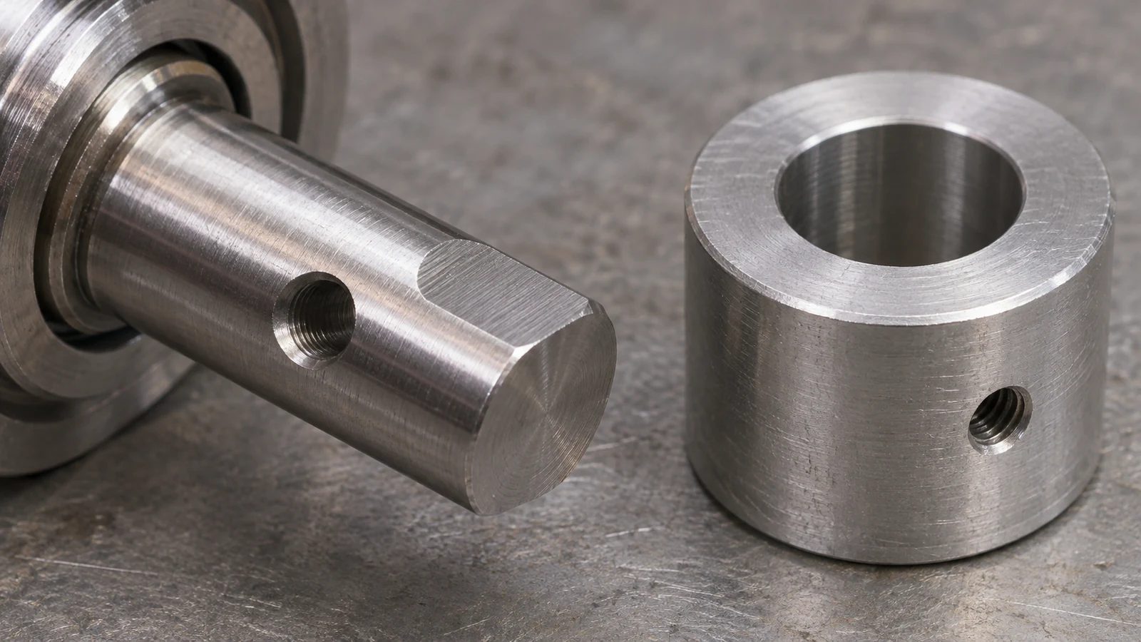
For rheostats, assembly and service conditions should drive the connection choice. A press fit, set screw, clamp hub, or pinned connection loads the shaft differently and may call for different end geometry. The responsible designer should determine required torque, retention force, and electrical clearances; the drawing should communicate those requirements instead of leaving a machining supplier to infer them. Dimension the selected connection from the shaft datum so the hub returns to a repeatable angular and axial position.
Relate turned and milled features to one axis
Turning establishes cylindrical features around a spindle axis; flats, slots and cross-holes are commonly produced in a milling or turn-mill operation. If these features control the same assembly, define how their orientation and position relate to the shaft axis and a functional end or shoulder. Otherwise a perfectly sized flat can still be clocked incorrectly, or a hole can sit at the right distance from an arbitrary end while missing the mating linkage.
Use a datum scheme that reflects how the shaft is located in the rheostat. The bearing or bushing diameter may establish the axis; an end face or shoulder may set the axial origin; a flat or another indexed feature may establish clocking. Avoid chains of dimensions when a direct relationship to the working axis and seating face is what the assembly needs. Do not add runout or concentricity controls by habit: identify the function they protect and the reference used to inspect them.

When features are machined in separate operations, setup transfer can affect their relationship. A drawing that clearly identifies the axis, shoulder and clocking reference gives the supplier a route to plan turning and milling together. For the general service scope, see обработанные валы, токарной обработки с ЧПУ и фрезерование с ЧПУ; the actual route depends on the specified geometry and project review.
Separate axial location from retention
A shoulder may establish where a shaft sits, while a snap-ring groove, thread, pin or clamp retains it. Those functions should not be conflated. Dimension the shoulder from the assembly datum and define the mating face it contacts. Then specify the retaining feature and its engagement separately. If the shaft must move axially during operation, state the required travel and the surfaces that limit it.
Journal length, surface condition and clearance matter where the shaft rotates inside a bushing. A fit that is acceptable for a stationary coupling may bind when it becomes a bearing interface. Identify the support material, lubrication or environmental conditions when they affect the design, and let the designer set the fit based on the full assembly. Do not use a generic “free fit” note as a substitute for a defined interface.
Edges at a bearing seat, shoulder or retaining groove deserve deliberate treatment. A broad edge-break note can remove material from a locating corner or make a retaining ring seat inconsistently. Call out a chamfer, radius or deburr limit only where the geometry requires it, and distinguish those edges from nonfunctional corners.
Select material and finish within the electrical boundary
Choose the shaft material for mechanical loading, wear, corrosion, weight, appearance and compatibility with mating parts. Aluminum, steel, stainless steel and brass can each suit different designs, but the alloy and condition must be named rather than inferred from color or a generic “metal” note. If a coating or plating is specified, clarify whether it applies to journals, threads, contact features or only visible surfaces.
Material and finish choices can change dimensions at the interface. A coating adds thickness; polishing removes material; heat treatment can affect a finished geometry. Identify the condition in which critical dimensions must be accepted and mark any surfaces that must be masked or protected. The site’s brass machining page is one example of material-specific considerations, not a recommendation for every rheostat. If the shaft participates in an electrical assembly, the rheostat designer must verify conductivity, insulation distances, grounding and safety requirements for the complete device. Machining a metal shaft does not certify those electrical characteristics.
Appearance can matter on an exposed control, but cosmetic requirements should be zoned. State the visible area, texture or color reference and acceptable handling marks. Keep cosmetic finishing distinct from the fit and rotation requirements so the supplier can plan inspection and protect functional surfaces during finishing.
Release a drawing a machine shop can verify
A useful package includes a controlled 2D drawing, a matching 3D model, units, revision, quantity, material and condition, finish, and the mating interfaces needed to interpret the shaft. Mark the axis datum, seating face, critical diameters, coupling geometry, axial locations, clocking and retention features. Identify inspection characteristics and explain how the assembly will be checked if a functional test is part of acceptance.
| Drawing item | What it resolves |
|---|---|
| Mating hub, rotor or bushing interface | Fit and engagement assumptions |
| Axis, end face and clocking datum | Position of flats, holes and shoulders |
| Retention and engagement length | How the actuator stays assembled |
| Material, condition and finish zones | Stock, secondary processing and protected surfaces |
| Acceptance method | How the supplier and buyer will judge the finished interface |
Ask the supplier to raise any unclear interface before cutting, especially if the only reference is an obsolete sample or an uncontrolled catalog drawing. Resolve deviations with the rheostat design authority and update the released drawing. A released drawing for rheostats should make the mechanical interfaces, material condition, and inspection basis clear. It defines a machinable shaft; the complete device still requires its own electrical design and qualification.