
Introdução: O Papel Crítico da Precisão na Usinagem de Suportes de Sensores
No mundo da medição e controle avançados, o sensor é tão bom quanto sua base. Um sensor, seja ele para medir vibração, temperatura, posição ou campos magnéticos, é um instrumento sofisticado projetado para detectar mudanças mínimas em seu ambiente. No entanto, sua capacidade de fornecer dados precisos e confiáveis é fundamentalmente comprometida se estiver fixado a um suporte mal fabricado. O processo de criação dessas interfaces críticas—usinagem de suporte de sensor—é uma disciplina onde a engenharia encontra a arte. É o herói anônimo da integridade dos dados, transformando matérias-primas em plataformas estáveis e precisas que garantem que um sensor funcione exatamente como pretendido. Sem essa precisão fundamental, o sensor mais caro e avançado pode produzir ruído enganoso em vez de sinal significativo, levando a decisões equivocadas em tudo, desde a segurança de aeronaves até a descoberta científica. Este artigo mergulha no mundo meticuloso da usinagem de suportes de sensores, explorando por que a precisão não é apenas uma meta, mas um requisito absoluto.
O que é Usinagem de Suporte de Sensor? Definindo o Processo e Seus Componentes
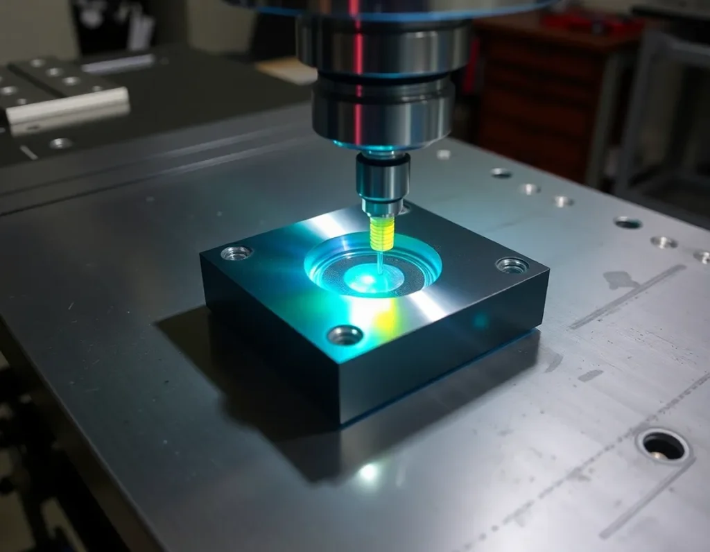
A usinagem de suporte de sensor é o processo de fabricação especializado de fabricar os componentes físicos que sustentam, posicionam e fazem a interface de um sensor com o sistema ou estrutura que ele monitora. Está muito além de simplesmente criar um suporte. Um suporte de sensor é um componente projetado para satisfazer um conjunto rigoroso de critérios mecânicos, térmicos e, às vezes, eletromagnéticos.
O processo normalmente começa com um projeto detalhado que considera os requisitos específicos do sensor e o ambiente operacional. Os usinadores então usam máquinas-ferramenta de precisão para remover material de um bloco sólido ou tarugo, moldando-o no suporte final. Os componentes principais de um sistema de suporte de sensor geralmente incluem:
- A Placa Base ou Interface: A superfície que se fixa diretamente à máquina, veículo ou estrutura de teste. Sua planicidade e precisão dos furos de montagem são cruciais para o alinhamento adequado e a transferência de carga.
- A Plataforma do Sensor: A área usinada com precisão onde o próprio sensor é montado. Esta superfície deve ter o acabamento, a planicidade e os recursos roscados ou com pinos corretos para fixar o sensor sem induzir tensão.
- A Estrutura de Ligação: O material que conecta a base à plataforma. Sua geometria é otimizada para máxima rigidez com massa mínima, frequentemente apresentando nervuras ou curvaturas complexas para resistir a forças de flexão e torção.
- Recursos de Alinhamento: Estes incluem furos de pino de cavilha de precisão, arestas de referência usinadas ou superfícies óticas planas que garantem que o sensor esteja orientado corretamente em relação ao eixo de medição.
- Conduítes e Passagens: Pequenos canais ou furos usinados para encaminhar cabos de sensores, linhas de refrigerante ou outros utilitários sem interferir na integridade estrutural do suporte.
Em última análise, usinagem de suporte de sensor é um processo integrativo que faz a ponte entre a capacidade teórica de um sensor e seu desempenho no mundo real, criando um componente passivo, porém vital, que possibilita ativamente medições precisas.
A Importância da Precisão: Por Que Tolerâncias e Estabilidade São Inegociáveis
A demanda por precisão extrema em suportes de sensores decorre de um princípio simples: o suporte não deve distorcer, amortecer ou alterar o sinal que o sensor está tentando captar. Qualquer imperfeição no suporte torna-se parte da medição, introduzindo erro. Dois conceitos são primordiais aqui: tolerâncias dimensionais e estabilidade dinâmica.
As tolerâncias — os limites permissíveis de variação em uma dimensão física — são frequentemente especificadas em milésimos de polegada (mils) ou até mícrons para características críticas. Por exemplo, se um sensor de deslocamento a laser exige que seus pés de montagem sejam coplanares dentro de 0,0005 polegadas para evitar desalinhamento ótico, o processo de usinagem deve atingir isso de forma confiável. Um desvio além dessa tolerância pode fazer o laser apontar ligeiramente fora do eixo, levando a erro de cosseno, em que a distância medida é maior que o deslocamento real. Da mesma forma, a posição verdadeira dos furos de montagem deve ser mantida com rigor para evitar condições de “aperto de parafuso” que podem empenar o suporte ou a carcaça do sensor durante a montagem, induzindo tensão de pré-carga que afeta as leituras.
A estabilidade, no entanto, vai além das dimensões estáticas. Refere-se à capacidade do suporte de manter sua geometria e propriedades sob condições operacionais. Os principais inimigos da estabilidade são vibração, variação térmica e carga. Um suporte deve ser rígido o suficiente para ter uma alta frequência natural, empurrando suas vibrações ressonantes bem acima da faixa de frequência que o sensor está medindo. Se a ressonância do suporte cair dentro da banda de medição, ela amplificará essas frequências, abafando os dados reais com ruído estrutural. Termicamente, o suporte deve resistir à expansão com materiais de baixo coeficiente ou ser projetado para expandir uniformemente sem distorcer a plataforma do sensor. A falta de estabilidade térmica pode causar deriva nas medições à medida que a temperatura ambiente muda. Em essência, um suporte usinado com precisão atua como um referencial silencioso e imutável, permitindo que o sensor faça seu trabalho sem interferência do próprio ambiente que ele está tentando quantificar.
Materiais Comuns para Suportes de Sensores: Do Alumínio ao Invar e Compósitos
A escolha do material é uma decisão fundamental no projeto de suportes de sensores, impactando diretamente o desempenho em termos de rigidez, peso, resposta térmica e custo. Os usinadores selecionam materiais com base em um equilíbrio cuidadoso dessas propriedades para atender à aplicação.
Ligas de Alumínio (por exemplo, 6061-T6, 7075-T6)
O alumínio é o material de trabalho para uma vasta gama de suportes de sensores. Ligas como a 6061-T6 oferecem uma excelente relação resistência-peso, boa usinabilidade e custo moderado. É adequado para a maioria das aplicações de uso geral em ambientes térmicos estáveis. A 7075-T6 proporciona maior resistência, aproximando-se de alguns aços, e é usada onde maior rigidez ou resistência à fadiga é necessária. O coeficiente de expansão térmica relativamente alto do alumínio (cerca de 23 µm/m·°C) pode ser uma limitação em aplicações de precisão com grandes variações de temperatura.
Aço Inoxidável (por exemplo, 304, 316, 17-4 PH)
O aço inoxidável é escolhido por sua resistência superior, resistência à corrosão e durabilidade. Graus como 304 e 316 são comuns em ambientes agressivos (marinho, químico). Graus de endurecimento por precipitação como o 17-4 PH podem ser tratados termicamente após a usinagem para atingir resistência muito alta e boa estabilidade dimensional. O aço é mais denso e pesado que o alumínio, e sua menor usinabilidade aumenta o tempo de fabricação e o desgaste da ferramenta. Seu coeficiente de expansão térmica é aproximadamente metade do do alumínio (cerca de 17 µm/m·°C), oferecendo melhor estabilidade térmica.
Invar (Fe-Ni36%)
For the most thermally critical applications, Invar is the gold standard. This nickel-iron alloy has an exceptionally low coefficient of thermal expansion (as low as 1.2 µm/m·°C), meaning it barely expands or contracts with temperature changes. This makes it indispensable for aerospace optical systems, satellite components, and scientific instruments where alignment must be maintained across extreme temperature gradients. However, Invar is expensive, dense, and can be challenging to machine, requiring specialized tools and techniques.
Titanium Alloys (e.g., Ti-6Al-4V)
Titanium offers a compelling combination of very high strength, low density, and excellent corrosion resistance. Its strength-to-weight ratio is superior to both aluminum and steel. While its thermal expansion is similar to stainless steel, its light weight and stiffness make it ideal for dynamic, weight-sensitive applications in aerospace and high-performance robotics. Like Invar, it is costly and presents machining challenges due to its low thermal conductivity and tendency to work-harden.
Engineered Composites and Ceramics
Advanced composites like carbon fiber reinforced polymer (CFRP) are used in ultra-high-performance applications. They can be engineered for near-zero thermal expansion in specific directions and offer an exceptional stiffness-to-weight ratio. Ceramics like silicon carbide provide extreme stiffness, low thermal expansion, and high thermal conductivity, making them ideal for stabilizing high-power laser systems. These materials often require non-traditional machining processes like waterjet cutting or diamond grinding.
Key Machining Processes and Technologies: CNC Milling, Turning, and Advanced Methods
The translation of a precise design into a physical reality relies on a suite of advanced machining technologies. Modern usinagem de suporte de sensor is dominated by computer numerical control (CNC), which provides the repeatability, complexity, and accuracy required.
Fresamento CNC
CNC milling is the most prevalent process for creating sensor mounts. A rotating cutting tool removes material from a stationary workpiece. Multi-axis CNC milling centers (3-axis, 4-axis, or full 5-axis) are essential for producing the complex geometries typical of optimized mounts. 5-axis machining, in particular, allows the tool to approach the workpiece from any direction in a single setup. This is critical for machining intricate ribbed structures, angled surfaces, and deep pockets without requiring multiple re-fixturing steps, each of which can introduce tiny alignment errors. The ability to machine a complete mount in one setup (“done-in-one”) is a key strategy for maximizing overall accuracy.
Torneamento CNC
CNC turning is used for producing cylindrical or rotationally symmetric components of a sensor mount system, such as adapter sleeves, spindle-mounted brackets, or kinematic coupling components. The workpiece rotates while a stationary cutting tool shapes it. Precision turning is capable of achieving extremely fine surface finishes and tight diametric tolerances. For mounts requiring both milled and turned features, CNC mill-turn centers combine both capabilities in one machine, allowing the complete machining of complex parts like a sensor housing with a cylindrical interface and a milled flat platform.
Advanced and Supporting Technologies
- Precision Grinding: Used as a finishing process to achieve surface finishes and flatness tolerances beyond the capability of even fine milling. Surface grinding and jig grinding are used to create optical-grade flat surfaces on the sensor platform and base interface.
- Usinagem por Descarga Elétrica (EDM): Particularly wire EDM, is invaluable for machining hard materials like Invar or hardened steel, or for creating sharp internal corners and complex profiles that would be impossible with a rotating cutter. It uses electrical sparks to erode material, leaving no mechanical stress.
- Coordinate Measuring Machine (CMM) Inspection: Integral to the process, not an afterthought. High-precision CMMs with touch probes or laser scanners are used to verify the geometry of the machined mount against the original CAD model. This ensures that all critical tolerances for flatness, parallelism, hole position, and size have been met.
- Stress-Relief Processes: To ensure long-term stability, machined components often undergo thermal or vibratory stress relief. This removes internal stresses trapped in the material from the machining process, which could otherwise cause the part to warp minutely over time or under temperature change, ruining its precision.
The synergy of these processes, guided by expert programming and metrology, enables the creation of sensor mounts that are not just metal shapes, but precision instruments in their own right.
Design Principles for Optimal Sensor Mounts: Rigidity, Thermal Management, and Alignment
The transition from raw material to a functional precision component is governed by foundational design principles. A successful sensor mount is not merely a bracket; it is a carefully engineered interface that must preserve the sensor’s intrinsic accuracy. Three pillars—structural rigidity, thermal management, and precise alignment—form the core of this design philosophy.
Rigidity, or stiffness, is paramount. Any flexure, vibration, or resonance in the mount translates directly into erroneous sensor readings. Designers combat this by optimizing geometry. This involves strategic use of ribbing, closed-box sections, and tapered forms to maximize the moment of inertia without adding excessive mass. The choice of material’s modulus of elasticity is critical here; a stiffer material like steel or Invar will resist deflection more effectively than a softer one, all else being equal. The goal is to push the mount’s natural resonant frequencies far above the operational vibration spectrum of the environment, ensuring the sensor sees only the motion it is intended to measure.
Thermal management is a silent but critical challenge. All materials expand and contract with temperature changes, a phenomenon quantified by the Coefficient of Thermal Expansion (CTE). An unmanaged CTE mismatch between the mount, the sensor, and the base structure can induce significant thermal stresses and cause dimensional drift, misaligning the sensor. Solutions are multi-faceted. First, material selection: using low-CTE alloys like Invar or matching the CTE of the mount to the sensor and underlying structure. Second, design: incorporating symmetric, thermally stable shapes and isolating heat sources with thermal breaks. In extreme precision applications, active thermal control through embedded cooling channels or heaters may be integrated directly into the mount’s design.
Alignment encompasses the absolute precision with which the sensor is positioned and oriented. This is defined by tolerances for flatness, perpendicularity, parallelism, and true position of mounting surfaces and fastener holes. Kinematic design principles are often employed for repeatable, stress-free location. This involves using precisely located spheres, grooves, and planes to deterministically constrain the six degrees of freedom of the sensor, eliminating over-constraint that can cause distortion. The design must also facilitate verification; it should include accessible datum features and clear reference surfaces that allow a Coordinate Measuring Machine (CMM) to unambiguously confirm all alignment specifications have been achieved during usinagem de suporte de sensor and assembly.
Applications Across Industries: Aerospace, Automotive, Robotics, and Scientific Research
The demand for precise sensor data transcends industry boundaries, making high-quality sensor mounts a ubiquitous, if often unseen, enabling technology. The specific requirements vary dramatically, showcasing the adaptability of advanced machining and design.
Aeroespacial e Defesa
In aerospace, sensor mounts operate in the harshest conceivable environments: extreme vibration during launch, radical thermal cycling from sunlight to shadow in space, and high G-forces during maneuvers. Mounts for inertial measurement units (IMUs), star trackers, and radar apertures must be exceptionally rigid and thermally stable to maintain navigation and targeting accuracy. Materials like titanium and beryllium-aluminum alloys are common for their high strength-to-weight ratio and stability. Every gram saved is crucial, leading to complex, lightweighted designs that are a testament to advanced 5-axis CNC milling and topology optimization software.
Automotive and Autonomous Vehicles
The rise of advanced driver-assistance systems (ADAS) and autonomous driving has turned modern vehicles into sensor platforms. Lidar, radar, and camera modules require mounts that maintain precise alignment through years of potholes, temperature swings, and vibration. Here, precision ensures system reliability and safety. Mounts are often designed for high-volume production, requiring machined prototypes for validation followed by investment cast or stamped production versions. The focus is on robust, cost-effective designs that guarantee the sensor’s field of view remains unobstructed and its calibration intact over the vehicle’s lifespan.
Robótica e Automação Industrial
Robotic systems rely on force/torque sensors, vision systems, and laser scanners to interact intelligently with their environment. A force sensor mount on a robotic wrist must be stiff to accurately transmit loads without hysteresis, while a mount for a vision camera on a fast-moving gantry must be both light and vibration-damped. In collaborative robotics, where humans work alongside machines, the absolute reliability of sensor data—hinging on a perfectly machined mount—is a direct safety imperative.
Scientific Research and Metrology
This domain pushes the limits of precision. In gravitational wave detectors like LIGO, mirror and sensor mounts are engineered to isolate components from vibrations at a sub-atomic scale. In synchrotrons and electron microscopes, mounts for X-ray detectors or sample holders require nanometer-level stability and repeatability. Materials like Invar, fused silica, and specialized composites are machined in ultra-clean, temperature-controlled environments. The design principles here are uncompromising, often incorporating monolithic (“flexure”) designs machined from a single block of material to eliminate sliding parts and the associated backlash or friction.
Challenges and Solutions in Sensor Mount Machining
Transforming a perfect design into a physical part is fraught with challenges. Recognizing and mitigating these issues is what separates competent machining from precision engineering.
Challenge 1: Maintaining Micro-Level Tolerances. Holding tolerances within a few microns over a large part or complex geometry is immensely difficult. Thermal effects from the cutting process, tool wear, and even the machine tool’s own thermal growth can cause drift.
Solução: Employing climate-controlled machining spaces, using coolant temperature management, and implementing in-process probing and tool wear compensation. Multi-step machining with intermediate stress relief and meticulous measurement ensures final dimensions are locked in.
Challenge 2: Machining Difficult Materials. Materials chosen for stability, like Invar or composites, can be notoriously difficult to cut. Invar work-hardens, composites are abrasive and cause delamination, and ceramics are brittle.
Solução: Specialized tooling is key. Polycrystalline diamond (PCD) tools for composites, sharp, positive-rake tools for Invar, and slow, careful machining strategies with high-pressure coolant. For the hardest materials, non-traditional processes like EDM become the primary rather than secondary operation.
Challenge 3: Avoiding and Managing Internal Stress. The machining process itself implants stress into the material. This latent stress can release over time or when the part is unclamped, causing distortion that ruins flatness and alignment.
Solução: A holistic approach. Starting with stress-relieved stock material, using symmetrical machining sequences to balance induced stresses, and employing gentle, consistent clamping forces. Crucially, performing intermediate and final thermal stress relief cycles to “season” the part and ensure long-term dimensional stability.
Challenge 4: Ensuring Repeatability in Production. For applications beyond one-off prototypes, producing dozens or hundreds of identical, precision mounts is its own challenge.
Solução: This is where process engineering shines. Creating detailed, validated machining protocols (including specific tools, speeds, feeds, and sequences), using qualified fixtures, and implementing rigorous statistical process control (SPC) with first-article and in-process inspections guarantee every part meets the exacting standard.
Resumo dos Pontos Principais
Sensor mount machining is the critical bridge between a sensor’s theoretical capability and its real-world performance. It is a specialized discipline that blends advanced manufacturing with precision engineering. The process demands an intimate understanding of materials, from common aluminum to exotic low-CTE alloys, and mastery of technologies like 5-axis CNC milling and EDM to create complex, stable geometries. The core design imperatives are unyielding rigidity, proactive thermal management, and fail-safe alignment, often realized through kinematic principles.
This expertise finds application across the technological spectrum, from ensuring the safety of autonomous vehicles and the accuracy of aerospace navigation to enabling the groundbreaking sensitivity of scientific instruments and the dexterity of advanced robotics. The field is defined by its challenges—holding micron tolerances, taming difficult materials, eliminating stress, and ensuring repeatability—each met with sophisticated solutions rooted in process control, metrology, and deep technical knowledge. Ultimately, a precision sensor mount is a testament to the fact that the fidelity of data is only as good as the physical foundation upon which it is gathered.
Perguntas Frequentes (FAQ)
What is the most important property to consider when choosing a material for a sensor mount?
There is no single “most important” property; it’s a balance based on application. However, the two primary contenders are specific stiffness (the ratio of Young’s modulus to density) for dynamic and weight-sensitive applications, and the Coefficient of Thermal Expansion (CTE) for applications subject to temperature variation. Often, a low CTE is the dominant requirement for ultimate precision, leading to the selection of materials like Invar despite their higher cost and weight.
Why can’t I just use a standard off-the-shelf bracket for my precision sensor?
Standard brackets are designed for general-purpose structural support, not for precision instrumentation. They typically lack the necessary rigidity, leading to vibration and deflection, and are not made from dimensionally stable materials. Their machining tolerances (flatness, hole position) are too loose, which can misalign the sensor and induce mounting stresses that affect its output. For any sensor where data accuracy is critical, a custom-designed and precision-machined mount is essential.
How are extremely flat mounting surfaces achieved during machining?
Achieving optical-level flatness involves multiple steps. First, a precision milling or fly-cutting operation creates the initial surface. This is often followed by grinding or lapping, which are abrasive processes that can achieve sub-micron flatness. Critically, the part must be stress-relieved before the final finishing pass to prevent future warping. The process is verified using optical flats, laser interferometers, or high-precision surface profilometers.
What is a kinematic mount, and when should it be used?
A kinematic mount uses a minimum set of contact points (typically balls, grooves, and planes) to constrain an object’s six degrees of freedom without over-constraint. This design guarantees repeatable, precise positioning and eliminates distortion caused by forcing parts together. It is ideal for applications requiring the sensor to be removed and reattached with absolute repeatability, such as in calibration fixtures, modular scientific instruments, or any interface where thermal expansion must occur without generating stress.
How much does a custom precision sensor mount typically cost?
Cost varies enormously based on complexity, material, tolerances, and quantity. A simple aluminum mount with moderate tolerances might cost a few hundred dollars for a prototype. A complex, large Invar mount for a scientific instrument, requiring extensive machining, stress relief, and CMM validation, can easily reach tens of thousands of dollars. The investment is justified by the value of the accurate, reliable data it enables the sensor to collect.