
Introduction : L'essor de la précision robotisée dans la fabrication
Pendant des décennies, l'atelier de fabrication a été dominé par le monde rigide, puissant et précis des machines CNC (commande numérique par ordinateur). Ces chevaux de trait ont défini la production de masse, offrant une précision inégalée pour les grandes séries. Cependant, une révolution silencieuse s'est développée, portée par le besoin d'une plus grande agilité et de la capacité à traiter des pièces plus grandes et plus complexes. Cette révolution est alimentée par la robotique, qui a évolué des simples manipulateurs de matériaux vers des centres d'usinage sophistiqués. La convergence de la technologie de capteurs avancée, de logiciels de programmation hors ligne puissants et de bras robotiques de haute précision a donné naissance à un nouveau paradigme : l'usinage des articulations robotiques. Cette approche ne consiste pas à remplacer purement et simplement la CNC, mais à repousser les limites de ce qui est possible, en apportant une précision automatisée à des tâches et des pièces autrefois considérées comme irréalisables ou trop coûteuses à automatiser. L'essor de la précision robotisée marque un passage vers des cellules de fabrication flexibles et reconfigurables, capables de s'adapter aux changements de produits avec un temps d'arrêt minimal, modifiant fondamentalement l'économie et les capacités de la production moderne.
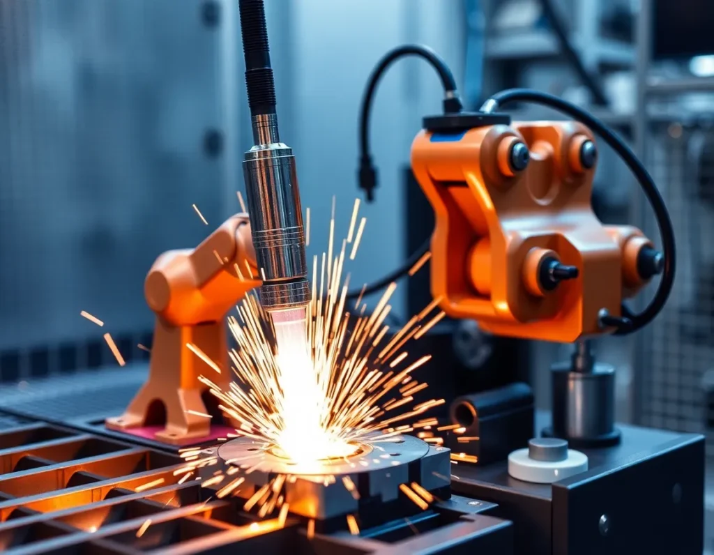
Qu'est-ce que l'usinage de joints robotisé ? Définition de la technologie de base
À la base, l'usinage de joints robotisé est un procédé de fabrication soustractive dans lequel un bras robotique industriel multiaxe, équipé d'une broche rotative et d'un outil de coupe, réalise des opérations d'usinage telles que le fraisage, le perçage, le défonçage, l'ébavurage ou le polissage. Le terme “ joint ” fait référence aux articulations rotatives articulées du bras robotique — généralement six ou plus — qui lui confèrent son amplitude de mouvement et sa dextérité. Contrairement à une machine CNC où l'outil de coupe se déplace le long de glissières linéaires (axes X, Y, Z), un système d'usinage robotisé déplace l'outil grâce à la coordination complexe de ses articulations rotatives. C'est cette structure cinématique qui confère au robot sa flexibilité exceptionnelle, lui permettant de manœuvrer les outils sous des angles non conventionnels et d'accéder à des espaces confinés sur des géométries grandes et complexes telles que des moules, des structures aérospatiales ou des composants architecturaux.
La technologie dépasse la simple automatisation. Un véritable système d'usinage de joints robotisé intègre plusieurs éléments critiques : le robot lui-même, une broche à haute fréquence capable des tr/min nécessaires pour la coupe, un capteur de force-couple pour le contrôle adaptatif, et un logiciel sophistiqué qui traduit un modèle CAO en une trajectoire d'outil impeccable et sans collision que le robot peut suivre. C'est cette intégration de la mécanique, de la détection et de l'intelligence qui définit l'usinage robotisé moderne, lui permettant d'aborder des matériaux allant des mousses souples et composites aux métaux comme l'aluminium et même l'acier avec une compétence croissante.
Composants et systèmes clés d'une cellule d'usinage robotisée
Une cellule d'usinage robotisée est un système synergique où chaque composant joue un rôle vital pour atteindre la précision et les performances requises. Comprendre ces éléments est essentiel pour saisir les capacités de la technologie.
Le manipulateur robotique
Il s'agit du bras articulé, l'élément physique d“” usinage de joints ». Les spécifications clés incluent la capacité de charge utile (pour porter la broche et résister aux forces de coupe), la portée, la répétabilité (souvent de l'ordre de ±0,05 mm à ±0,1 mm pour les modèles d'usinage) et la rigidité. Des robots robustes à structure renforcée sont généralement choisis pour minimiser la déformation pendant la coupe.
Broche et outillage
La broche est le cœur de l'action de coupe. Les broches d'usinage robotisées sont généralement des unités à haute fréquence (souvent 20 000 tr/min et plus), à entraînement électrique, qui fournissent la vitesse et la puissance nécessaires à l'enlèvement de matière. Elles sont montées sur la bride d'outillage en bout de bras (EOAT) du robot. Des changeurs d'outils automatiques (ATC) sont fréquemment intégrés pour permettre à un seul robot d'effectuer plusieurs opérations — perçage, puis fraisage, puis ébavurage — sans intervention manuelle.
Système de contrôle et logiciel
C'est le cerveau de l'opération. Il se compose du contrôleur du robot et, surtout, de logiciels avancés de programmation hors ligne (OLP) et de simulation. Le logiciel OLP permet aux programmeurs de créer, d'optimiser et de simuler l'ensemble du processus d'usinage dans un environnement 3D virtuel. Il génère le code complexe qui coordonne toutes les articulations du robot pour déplacer l'outil le long de la trajectoire précise, tout en simulant les temps de cycle et en vérifiant les collisions avec la pièce, les fixations ou le robot lui-même.
Systèmes de détection et de rétroaction
Pour compenser la rigidité intrinsèquement plus faible d'un robot à liaison série par rapport à une machine CNC, les cellules avancées utilisent des systèmes de rétroaction en temps réel. Un capteur de force-couple monté entre le poignet du robot et la broche mesure les forces de coupe. Ces données sont transmises à un système de contrôle adaptatif qui peut ajuster dynamiquement la vitesse d'avance ou la trajectoire du robot afin de maintenir des conditions de coupe optimales, évitant ainsi la rupture de l'outil et garantissant une qualité constante, en particulier sur les pièces présentant des variations inconnues.
Maintien de la pièce et axes externes
La pièce doit être fixée de manière sécurisée, souvent à l'aide de fixations modulaires. Pour l'usinage de très grandes pièces ou pour obtenir des orientations spécifiques, la pièce peut être montée sur un positionneur motorisé ou une table tournante (un axe externe). Cela augmente effectivement les degrés de liberté du système, permettant au robot d'accéder à toutes les faces d'une pièce sans la refixer, ce qui améliore considérablement l'efficacité pour les composants complexes.
Les avantages de l'usinage robotisé multi-axes : précision, flexibilité et coût
L'adoption de l'usinage robotisé multi-axes est motivée par un ensemble d'avantages convaincants qui répondent aux principaux défis de la fabrication moderne.
Flexibilité et enveloppe de travail inégalées : C'est le principal avantage. Un robot standard à 6 axes peut manipuler un outil autour d'une pièce d'une manière qu'une machine CNC à 3 axes, voire à 5 axes, ne peut pas, en atteignant des cavités profondes ou en usinant selon des angles composés prononcés. L'enveloppe de travail — l'espace physique auquel le robot peut accéder — est également nettement plus grande pour un encombrement et un coût donnés par rapport à une machine CNC. Cela rend les robots idéaux pour de très grandes pièces telles que les pales d'éoliennes, les coques de bateaux ou les sections d'aéronefs, qui nécessiteraient un portique CNC colossal et sur mesure.
Rentabilité pour les grandes pièces et les volumes faibles à moyens : L'investissement en capital pour une cellule robotisée est souvent inférieur à celui d'une machine CNC de taille équivalente. Pour l'usinage de grandes pièces, les économies sont spectaculaires. De plus, les robots excellent dans la production à volume faible à moyen et à forte mixité. Une seule cellule robotisée peut être rapidement reprogrammée et rééquipée pour effectuer différentes opérations sur différentes pièces, maximisant l'utilisation des actifs et permettant une production économique en petits lots.
Intégration transparente dans les lignes automatisées : Un robot est intrinsèquement conçu pour l'automatisation. Une cellule d'usinage robotisée peut être facilement intégrée à d'autres robots pour le chargement/déchargement des pièces, à des systèmes de vision pour la localisation des pièces, ou à des convoyeurs pour créer une ligne de production entièrement automatisée. Cela crée un flux continu de la matière première à la pièce finie avec une manipulation humaine minimale.
Réduction du temps non productif et finition complexe : Les robots peuvent effectuer plusieurs processus en un seul montage. Après le fraisage, le même robot peut automatiquement passer à un patin de ponçage ou à une meule de polissage pour finir la surface, éliminant le temps et les inexactitudes potentielles liés au déplacement de la pièce vers un poste séparé. Leur dextérité les rend également parfaits pour des tâches fastidieuses et laborieuses comme l'ébavurage ou la création de finitions esthétiques constantes sur des contours complexes.
Applications courantes et industries transformées par l'usinage robotisé
The unique strengths of robotic joint machining have made it a transformative technology across several key industries.
- Aerospace and Defense: This industry is a major adopter. Robots are used to trim and drill composite panels for aircraft fuselages and wings, machine large aluminum structural frames, and polish complex turbine blades. The ability to handle large, lightweight structures with precision is critical.
- Automotive (Prototyping, Tooling, and Composites): Beyond assembly line welding, robots machine full-scale clay models for vehicle design, create molds and dies for body panels, and trim composite parts for high-end and electric vehicles. Their flexibility speeds up the prototyping and tooling phases dramatically.
- Marine and Transportation: Building ships, trains, and buses involves massive components. Robots rout and cut fiberglass for boat hulls, machine interior panels for rail cars, and prepare large metal weldments, all tasks where size makes traditional CNC impractical.
- Architecture and Construction: The trend towards prefabrication and complex architectural forms (façades, sculptural elements) relies on robotic machining to shape wood, stone, composites, and foam into precise, bespoke components.
- Wind Energy: Manufacturing giant wind turbine blades from fiberglass requires precise trimming of excess material and drilling of root sections. Robotic cells are the only feasible method for automating this process on such a scale.
- General Fabrication and Pattern/Mold Making: Job shops and foundries use robots to machine patterns for casting from foam or wood, and to produce molds for composite layup or plastic injection molding, benefiting from the flexibility to switch between jobs quickly.
The Robotic Machining Process: From CAD Model to Finished Part
The journey from a digital design to a physically machined part via a robot follows a meticulous, software-driven workflow.
Step 1: CAD Model and Toolpath Generation
It all begins with a 3D CAD model of the final part. This model is imported into specialized CAM (Computer-Aided Manufacturing) software, often integrated within the robot’s offline programming suite. Here, the programmer defines the machining operations: selecting tools, specifying cutting speeds, feed rates, and depth of cut. The software then calculates the precise toolpath the cutting tool must follow to create the part geometry.
Step 2: Offline Programming and Simulation
This is the critical phase unique to robotics. The toolpath data, along with 3D models of the robot, spindle, tooling, workholding, and the raw material (blank), are loaded into the simulation environment. The programmer builds the virtual cell, positioning all elements exactly as they exist in the real world. The software then simulates the entire machining process. It checks for reachability, ensures the robot joints do not exceed their limits, and performs rigorous collision detection between all moving and static elements. The path is optimized for smooth motion and cycle time.
Step 3: Post-Processing and Code Generation
Once the simulation is perfect, the software “post-processes” the path data. This translates the universal toolpath instructions into specific code (e.g., RAPID, KRL, URScript) that the brand-specific robot controller can understand. This code contains the thousands of coordinated joint position commands that will drive the robot.
Step 4: Cell Setup and Calibration
In the physical world, the workpiece is securely mounted. Critical calibration is performed to align the robot’s coordinate system with the real-world position of the part. Techniques like using a probe to touch off known points on a fixture ensure the virtual world and physical world match perfectly—a prerequisite for accuracy.
Step 5: Machining Execution with Adaptive Control
With the program loaded and the cell calibrated, machining begins. In advanced systems, the force-torque sensor provides real-time feedback. If the tool encounters unexpected hard material or begins to vibrate, the adaptive controller can instantly adjust the feed rate to compensate, protecting the tool and ensuring a quality finish. This closed-loop control is what elevates robotic machining from a simple playback system to an intelligent manufacturing process.
Step 6: Finishing and Inspection
Following the primary material removal, the robot may automatically change tools to perform secondary finishing operations. Post-machining, inspection—sometimes using the same robot equipped with a touch probe or laser scanner—can be conducted to verify critical dimensions, closing the digital-physical loop.
Critical Considerations: Choosing Between Robots and Traditional CNC Machines
The decision to implement robotic joint machining or stick with a traditional CNC machine is not a simple one. It hinges on a nuanced understanding of each technology’s inherent strengths and the specific demands of the production task. While CNC machines are the undisputed champions of ultra-high precision and heavy material removal, robots offer a unique blend of flexibility, reach, and cost-effectiveness for a different set of challenges.
Traditional CNC machines—milling centers, lathes, and grinders—are built on a foundation of massive, rigid cast iron or polymer concrete structures. This inherent stiffness allows them to wield powerful spindles, take deep cuts in hard metals like titanium or Inconel, and maintain micron-level tolerances across a part. Their work envelope is precisely defined by the axes of the machine itself, typically three to five linear axes. For high-volume production of complex metal components where absolute dimensional perfection is non-negotiable, a CNC machine is often the only suitable choice.
Robotic machining cells, in contrast, trade some of that raw stiffness for a dramatically larger and more flexible working volume. A standard six-axis industrial robot can manipulate a spindle around a part that is much larger than the robot’s own footprint, accessing angles and interiors that would be impossible for a gantry-style CNC. This makes l'usinage des articulations robotiques ideal for “subtractive manufacturing” on large, non-metallic components. Think of trimming composite aircraft fuselages, sculpting large polymer molds, or de-flashing aluminum castings. The robot is not trying to out-mill a CNC on a steel gear; it is performing precise machining operations on parts that are too big, too awkward, or too soft for a conventional machine tool.
The economic calculation is also distinct. For dedicated, high-volume metal cutting, a CNC’s speed and precision justify its high capital cost. A robotic cell, however, offers a lower entry cost for large-part machining and unparalleled flexibility. The same robot that performs trimming in the morning can be re-tooled for drilling in the afternoon and sanding in the evening. This makes it perfect for lower-volume, higher-mix production, prototype development, or for finishing operations on large components post-casting or forming. The choice ultimately maps to a simple matrix: prioritize absolute precision and material hardness? Choose CNC. Prioritize envelope size, material versatility (like composites, wood, foam), and flexible automation? The robot becomes a compelling contender.
Overcoming Challenges: Vibration, Stiffness, and Path Accuracy
The flexibility of a serial-link robot arm—the very thing that gives it a large work envelope—is also the source of its primary technical challenges. Unlike the monolithic structure of a CNC, a robot is a chain of links connected by joints, each with a degree of compliance. This can lead to issues of vibration, lack of stiffness, and path inaccuracy under load, which the industry has aggressively tackled with both mechanical and software solutions.
Addressing Structural Stiffness and Chatter
When a cutting tool engages material, it generates significant cutting forces. On a compliant robot arm, these forces can cause deflection—the arm bends slightly—leading to dimensional errors and, critically, tool chatter. Chatter is a violent vibration that ruins surface finish and rapidly destroys cutting tools. To combat this, robotic machining systems are designed with several key features. First, robots selected for machining are typically of a heavier payload class (e.g., 50kg to 500kg) than needed just to carry the spindle, providing a more robust structure. Second, the spindle and tool holder are mounted as close to the robot’s base as possible, often on the second or third axis, to minimize the lever arm effect. Third, external force-torque sensors mounted at the wrist provide real-time feedback to an adaptive controller, which can dynamically adjust feed rates to keep forces within a stable window.
Enhancing Path Accuracy and Repeatability
A robot’s native programming tells it to move its joints to a certain position in space, but this does not guarantee the tool tip follows the exact, smooth path required for precision contouring. Factors like gear backlash, link deflection, and temperature drift introduce errors. Advanced calibration is the answer. Using a laser tracker or a similar metrology system, technicians can map the robot’s kinematic errors across its entire work volume, creating a compensation file that corrects the robot’s internal model. This process, often called “absolute accuracy calibration,” can improve a robot’s positioning accuracy from several millimeters down to a fraction of a millimeter. Furthermore, real-time path correction software uses data from the force sensor or even a secondary measurement system to make micro-corrections to the tool path on the fly, ensuring it adheres to the programmed trajectory despite physical deviations.
System Integration for Stability
The overall stability of a robotic machining cell extends beyond the robot itself. The workpiece must be fixtured with exceptional rigidity to prevent any movement. The cutting tools used are often specialized—featuring variable helix angles and polished flutes—designed to reduce cutting forces and promote smooth chip evacuation. By viewing the robot, spindle, tool, fixture, and control software as a single integrated system, engineers can tune out vibrations and achieve levels of precision that were once thought impossible for an industrial robot.
The Future of Robotic Joint Machining: AI, Adaptive Control, and Hybrid Systems
The trajectory of robotic joint machining points toward ever-greater intelligence, autonomy, and integration. The goal is to move from a process that requires extensive expert programming and tuning to one where the system can perceive, decide, and adapt in real-time, closing the gap with the deterministic performance of CNC while retaining its flexible advantages.
Artificial Intelligence and machine learning are poised to revolutionize process optimization. Instead of relying solely on pre-defined parameters, AI algorithms can analyze data streams from force sensors, acoustic emission sensors, and even cameras to identify optimal cutting conditions. They can learn to predict and prevent chatter before it starts, recommend ideal toolpaths for minimal stress, and predict tool wear, scheduling maintenance before quality degrades. This transforms the robot from a blind executor into a learning, optimizing partner.
Adaptive control will evolve from simple force-feedback loops to multi-sensor, model-predictive systems. Future controllers will not only react to forces but will also process real-time visual data from in-process inspection. Imagine a robot machining a rough casting: a 3D scanner constantly maps the as-cast surface, and the controller dynamically adjusts the toolpath to ensure a consistent finish cut, regardless of the casting’s initial dimensional variance. This “first-part-correct” capability would eliminate hours of manual programming for one-off parts.
Perhaps the most significant trend is the rise of hybrid manufacturing systems. Here, robotic joint machining is integrated with additive processes like directed energy deposition (DED) or wire arc additive manufacturing (WAAM). In these cells, a robot builds up a part layer by layer using a welding process, then automatically switches tools to a milling spindle to machine critical features to tolerance. This blend of additive and subtractive processes in a single, flexible work cell allows for the creation of complex, low-volume parts with internal geometries that are impossible to produce by machining alone. The future factory floor will likely feature these multi-function robotic cells as standard, capable of building, trimming, drilling, and inspecting a part in a single, automated setup.
Résumé des points clés
Robotic joint machining has established itself as a transformative force in modern manufacturing, not as a replacement for traditional CNC, but as a complementary technology that excels in a different domain. Its core value lies in applying precise subtractive processes to large, complex, or non-rigid materials where conventional machines are impractical.
- Core Definition: It is a process where an industrial robot, equipped with a spindle and cutting tool, performs milling, drilling, trimming, and finishing operations, leveraging its multi-axis flexibility for complex part geometries.
- System Components: A complete cell integrates the robot arm, an end-effector (spindle), a robust controller, often a force-torque sensor, and specialized software for programming, simulation, and path correction.
- Primary Advantages: The technology offers unmatched flexibility for large work envelopes, lower capital cost for big-part machining, and the ability to be quickly re-tooled for different tasks, making it ideal for high-mix, lower-volume production.
- Key Applications: It thrives in aerospace (composite trimming), automotive (casting deflashing), foundries (mold finishing), and sculpture (large-scale prototyping), handling materials from composites and aluminum to wood and foam.
- The Process Workflow: It follows a digital thread from CAD/CAM programming and offline simulation to physical calibration, adaptive machining execution, and often in-situ inspection.
- Choosing the Right Tool: The choice between robot and CNC hinges on the trade-off between absolute precision/material hardness (CNC) and envelope size/material flexibility/automation versatility (Robot).
- Overcoming Challenges: Through heavy-duty robots, advanced kinematic calibration, real-time path correction, and adaptive force control, the industry has successfully mitigated traditional issues of robot stiffness, vibration, and path inaccuracy.
- The Future Trajectory: The field is advancing through the integration of AI for process optimization, more sophisticated adaptive control using multi-sensor feedback, and the development of hybrid systems that combine additive and subtractive processes in a single, autonomous robotic cell.
In essence, robotic joint machining is the bridge between the rigid, high-precision world of CNC and the flexible, dynamic world of industrial automation, opening new possibilities for how we manufacture large and complex components.
Frequently Asked Questions (FAQ)
How accurate is robotic joint machining compared to a 5-axis CNC mill?
While modern robotic machining systems have made tremendous strides, a high-end 5-axis CNC mill generally offers superior absolute accuracy and repeatability, often in the single-digit micron range. A well-calibrated robotic machining cell can typically achieve positional accuracy around 0.1 mm to 0.5 mm, with path accuracy improved through real-time correction. The key distinction is application: for machining hardened steel to micron tolerances, CNC wins. For trimming a carbon fiber aircraft wing to a tolerance of ±0.2 mm, the robot is perfectly capable and far more practical.
Can robots machine hard metals like steel or titanium?
Yes, but with important caveats. Robotic machining of hard metals is possible and is done in applications like weld seam grinding or light finishing. However, it is not typically used for heavy bulk material removal in these metals. The process requires a very rigid robot (often a specialized “machining robot” with a stiffer arm design), conservative cutting parameters (lighter depths of cut, slower feed rates), and excellent adaptive force control to prevent tool deflection and chatter. For most high-volume metal cutting, CNC remains more efficient.
What is the role of the force-torque sensor in the process?
The force-torque sensor, mounted between the robot’s wrist and the spindle, is the critical component for adaptive control. It acts as the robot’s “sense of touch,” measuring the exact forces and torques being applied to the tool during cutting. This real-time data is fed to the controller, which can instantly adjust the robot’s speed or path to maintain a constant, optimal cutting force. This protects the tool from breakage, compensates for material variation or part misalignment, and enables processes like precise deburring and contour following.
Is offline programming essential for robotic machining?
For any complex or production-level robotic machining task, offline programming (OLP) is not just beneficial—it is virtually essential. Programming intricate 3D toolpaths by manually jogging the robot is impractical and unsafe. OLP software allows programmers to create, simulate, and optimize the entire machining process in a virtual environment. They can check for collisions, optimize robot posture for stiffness, and generate efficient code without taking the physical cell offline, dramatically reducing programming time and ensuring a safe, validated program from the first run.
What are hybrid manufacturing systems, and how do they relate to robotic machining?
Hybrid manufacturing systems combine additive (building up material) and subtractive (machining away material) processes within a single automated work cell, often centered on an industrial robot. The robot might use a metal deposition head (like a welding torch) to build a part layer by layer, then automatically switch to a milling spindle to machine precise features, holes, and surfaces. Robotic joint machining is the subtractive heart of this concept. This hybrid approach allows for the creation of complex, near-net-shape parts with internal geometries that are impossible to achieve through machining alone, all with minimal setup.