
Le rôle critique de l'usinage de précision dans le refroidissement des puces d'IA
L'avancement incessant de l'intelligence artificielle repose sur une fondation de silicium, mais son véritable potentiel n'est libéré que lorsque ce silicium peut fonctionner à des performances optimales. Les puces d'IA, le cerveau derrière l'apprentissage automatique, les réseaux neuronaux profonds et l'analyse de données complexes, consomment d'énormes quantités d'énergie électrique. Cette énergie n'est pas convertie en pure computation ; une partie significative devient de la chaleur résiduelle. Si cette énergie thermique n'est pas gérée avec une efficacité extrême, elle entraîne une réduction des performances, une durée de vie réduite et une défaillance catastrophique. C'est là qu'entre en scène le héros méconnu de la révolution de l'IA : le dissipateur thermique usiné de précision. Le processus d' usinage des dissipateurs thermiques pour puces d'IA n'est pas simplement une étape de fabrication ; c'est une discipline d'ingénierie critique qui comble le fossé entre la puissance de calcul théorique et un fonctionnement pratique et fiable. Sans la précision au niveau du micron et la conception thermique avancée permises par l'usinage moderne, les processeurs denses et à haute puissance qui alimentent l'IA fondraient simplement sous leur propre charge thermique. Le rôle de l'usinage est donc fondamental, transformant les matières premières en conduits thermiques sophistiqués qui sont aussi vitaux pour le fonctionnement du système que les transistors sur la puce elle-même.
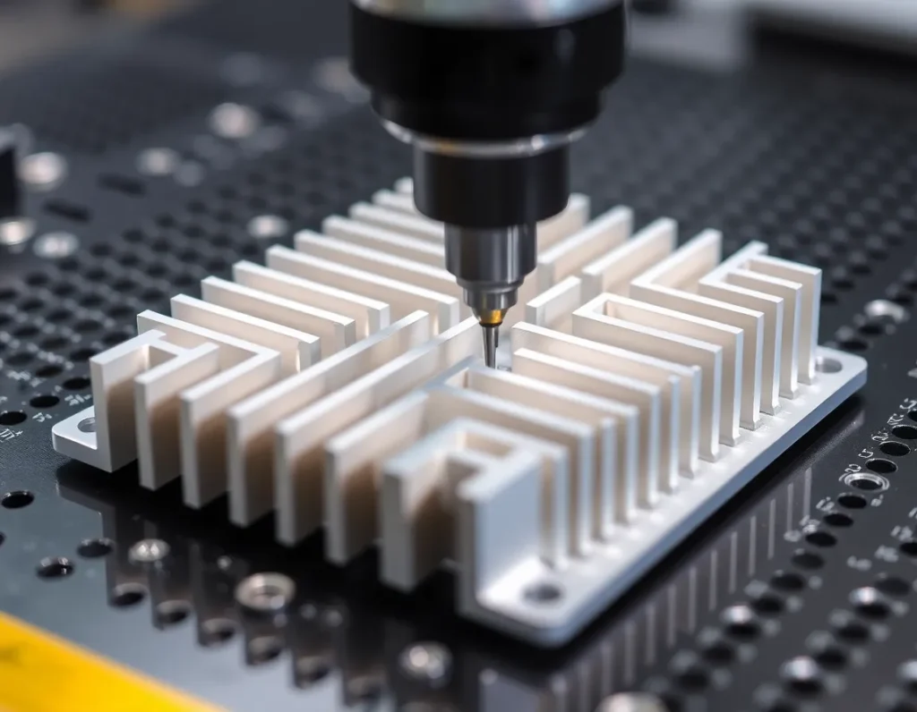
Qu'est-ce que l'usinage des dissipateurs thermiques pour puces d'IA ? Définition du processus et de ses composants
L'usinage des dissipateurs thermiques pour puces d'IA est un sous-ensemble spécialisé de la fabrication de précision axé sur la création des composants métalliques qui se fixent physiquement à un processeur d'IA pour évacuer la chaleur de sa puce de silicium délicate. À la base, il s'agit du processus soustractif consistant à façonner des blocs ou des feuilles de métaux à haute conductivité thermique en géométries complexes avec des tolérances rigoureuses. Le produit final est bien plus qu'un simple morceau de métal ; c'est une solution thermique intégrée comprenant plusieurs composants clés. La plaque de base, souvent plane comme un miroir, établit un contact intime avec la puce. Les ailettes, qui peuvent être obtenues par rabotage, fraisage ou forgeage, augmentent considérablement la surface exposée à l'air ou au liquide de refroidissement. Des caloducs ou des chambres à vapeur sont fréquemment intégrés à l'ensemble pour répartir rapidement la chaleur d'un point chaud concentré sur toute la matrice d'ailettes. Le processus d'usinage définit l'intégrité de l'interface thermique, l'efficacité de la structure des ailettes et la robustesse globale de la solution de refroidissement. C'est une convergence de l'ingénierie mécanique, de la science des matériaux et de la physique thermique, exécutée avec une précision contrôlée par ordinateur pour répondre aux spécifications uniques et exigeantes du matériel d'IA.
Pourquoi les puces d'IA exigent des dissipateurs thermiques avancés : l'impératif de la gestion thermique
Le défi thermique posé par les puces d'IA modernes est sans précédent dans l'histoire de l'informatique. Les CPU et GPU traditionnels génèrent une chaleur substantielle, mais les accélérateurs d'IA—comme les GPU (Graphics Processing Units) et les TPU (Tensor Processing Units)—poussent les densités de puissance à de nouveaux extrêmes. Ces puces sont conçues pour le traitement parallèle d'opérations matricielles massives, une tâche qui maintient des milliards de transistors actifs simultanément. Cette orientation architecturale conduit à des valeurs de puissance de conception thermique (TDP) pouvant dépasser 700 watts dans un seul boîtier, avec des densités de flux thermique concentrant cette puissance dans des zones parfois plus petites qu'un timbre-poste. Les solutions de refroidissement conventionnelles deviennent totalement inadéquates. Un dissipateur thermique avancé pour une puce d'IA doit accomplir plusieurs exploits : il doit absorber une chaleur intense d'une zone minuscule presque instantanément, répartir cette chaleur latéralement pour éviter la surchauffe localisée (un phénomène connu sous le nom de “ point chaud ”), puis la rejeter dans l'environnement avec une efficacité maximale. Une défaillance à n'importe quel point de cette chaîne oblige la puce à réduire sa fréquence pour se protéger, sacrifiant directement la vitesse de calcul—la mesure même qu'elle est conçue pour maximiser. Par conséquent, la gestion thermique avancée via des dissipateurs thermiques usinés de précision n'est pas un luxe ; c'est un impératif absolu pour maintenir l'intégrité, les performances et le retour sur investissement des clusters d'entraînement d'IA et des serveurs d'inférence à plusieurs milliards de dollars.
Processus d'usinage essentiels pour les dissipateurs thermiques d'IA : fraisage CNC, rabotage et forgeage
Pour répondre aux exigences strictes de la gestion thermique de l'IA, les fabricants emploient une suite de processus d'usinage avancés, chacun sélectionné pour des exigences spécifiques de performance et de géométrie.
Fraisage CNC
Le fraisage à commande numérique par ordinateur (CNC) est le cheval de trait polyvalent de la fabrication de dissipateurs thermiques. À l'aide de machines multi-axes, les outils de coupe sculptent un bloc de métal massif en formes complexes avec des tolérances mesurées en microns. Ce processus est idéal pour créer des géométries de plaque de base uniques, des caractéristiques de montage complexes et des canaux intégrés pour le refroidissement liquide. Pour les dissipateurs thermiques d'IA, le fraisage CNC 5 axes permet la création d'ailettes coniques et de contre-dépouilles qui seraient impossibles avec l'usinage standard, optimisant à la fois le flux d'air et l'intégrité structurelle. La précision du fraisage CNC garantit une base parfaitement plane pour un contact optimal avec la puce, une exigence non négociable pour un transfert de chaleur efficace.
Rabotage
Le rabotage, ou scarification, est un processus spécialisé qui produit des ailettes exceptionnellement fines à rapport d'aspect élevé à partir d'un seul bloc de métal. Une lame tranchante et précise pèle une fine couche de métal d'une base monolithique, la soulevant pour former une ailette continue. Cela crée une structure d'une seule pièce où les ailettes font partie intégrante de la base, éliminant la résistance thermique présente au niveau du joint entre des ailettes fixées séparément. Les dissipateurs thermiques rabotés offrent un excellent équilibre entre une grande surface et une robustesse structurelle, ce qui en fait un choix populaire pour les systèmes d'IA refroidis par air à hautes performances. La densité et la finesse des ailettes rabotées maximisent la dissipation thermique dans un encombrement volumétrique restreint.
Forging
Forging involves shaping metal under immense pressure, either hot or cold. For heatsinks, forging is often used to create strong, dense fin arrays with excellent grain structure. The process enhances the mechanical and thermal properties of the metal by aligning the grain flow with the shape of the fins. Forged heatsinks are known for their durability and reliability, often used in applications where mechanical shock or vibration is a concern. While the fin density might not reach that of skived parts, forged heatsinks provide outstanding structural performance and consistent quality for high-volume production runs common in data center applications.
Often, these processes are combined. A heatsink may feature a CNC-milled base with embedded heat pipes, topped with a skived or forged fin stack, creating a hybrid solution that leverages the strengths of each technique.
Material Selection for High-Performance AI Heatsinks: Copper, Aluminum, and Composites
The choice of material is a fundamental thermal and economic decision in usinage des dissipateurs thermiques pour puces d'IA. The primary contenders each offer a distinct set of trade-offs between conductivity, weight, cost, and manufacturability.
Cuivre
Copper is the gold standard for thermal conductivity, offering approximately 60% better heat transfer than aluminum. This makes it the preferred material for the most demanding AI cooling applications, particularly for components like base plates and vapor chambers that must rapidly absorb and spread heat from concentrated hotspots. Its superior conductivity comes with drawbacks: copper is significantly heavier (roughly three times the density of aluminum) and more expensive, both in raw material cost and in machining difficulty due to its gummy nature. However, for the highest thermal performance, especially in liquid cooling cold plates or direct-die cooling solutions, copper’s advantages are often indispensable.
Aluminium
Aluminum alloys are the most common material for volume heatsink production, offering an excellent balance of performance, weight, and cost. While its thermal conductivity is lower than copper’s, it is still highly effective, especially when combined with good design to increase surface area. Aluminum is much lighter, easier to machine at high speeds, and more corrosion-resistant. For many AI server applications where weight and cost are critical factors, and where cooling can be augmented by powerful fans or liquid loops, aluminum heatsinks provide a highly optimized solution.
Composites and Advanced Alloys
To push beyond the limitations of pure metals, the industry is turning to advanced materials. These include aluminum matrix composites (e.g., aluminum infused with diamond or silicon carbide particles) which can offer thermal conductivity approaching or exceeding that of copper while retaining a lower density. Vapor chamber materials are also evolving, with thinner walls and more efficient wick structures. Furthermore, thermal interface materials (TIMs)—the paste, pads, or liquid metal between the chip and heatsink—are a critical “material” in the system. Advances in TIMs, such as graphene-infused compounds or phase-change materials, directly impact the effectiveness of the entire heatsink assembly by minimizing the thermal barrier at the most critical junction.
Design and Engineering Considerations for Optimal Thermal Performance
Creating an effective AI heatsink is an exercise in multi-disciplinary optimization, where mechanical, thermal, and aerodynamic design must converge.
The thermal resistance network is the central concept. Engineers must minimize resistance at every point: from the silicon die, through the thermal interface material, into the heatsink base, along the fins, and finally into the coolant (air or liquid). The base thickness and area are calculated to spread heat without becoming a bottleneck. Fin geometry—height, thickness, spacing, and shape—is optimized using computational fluid dynamics (CFD) to maximize heat transfer for a given fan power and acoustic signature. In air-cooled designs, fin alignment relative to airflow is critical; parallel fin stacks are common, but staggered or pin-fin arrays can enhance turbulence and heat transfer in constrained spaces.
For liquid-cooled systems, the design shifts to cold plates. Here, the internal microchannel structure is paramount. The pattern, width, and depth of these channels dictate flow resistance and heat exchange efficiency. Designs must balance high turbulence for good heat transfer with low pressure drop to minimize pump power. Jet impingement cooling, where fluid is directed in high-velocity streams directly at the back of the chip’s hotspot, represents another advanced design approach for the most extreme thermal loads.
Mounting pressure and flatness are critical mechanical considerations. Insufficient pressure leads to high thermal interface resistance, while excessive pressure can warp the chip substrate or heatsink. A machined flatness measured in microns across the base ensures full contact. Finally, the entire design is constrained by the physical envelope of the server chassis, requiring innovative 3D packaging to fit maximum cooling capacity into minimal space. This holistic engineering effort transforms a passive metal component into an active, system-level thermal management solution.
Surface Finishing and Coating Techniques to Enhance Heat Dissipation
The journey of an AI heatsink does not end with precision machining. The final surface condition of the metal plays a decisive role in its thermal performance. A mirror-smooth finish might seem ideal, but for maximizing heat dissipation, controlled roughness and specialized coatings are often the true heroes. These post-machining processes target the two primary thermal resistances: the interface between the chip and heatsink base, and the interface between the fins and the cooling medium.
Starting at the base, the mounting surface that contacts the AI chip must be exceptionally flat to minimize air gaps. Machining achieves this flatness, but the microscopic peaks and valleys left by the cutting tool can trap air, a poor thermal conductor. Lapping is a common finishing technique used to create an optically flat surface, often specified with a roughness average (Ra) in the range of 0.1 to 0.8 micrometers. This ultra-smooth surface ensures maximum contact area for the thermal interface material (TIM), such as grease or a phase-change pad, leading to lower thermal resistance.
Conversely, the fin surfaces and other areas exposed to air or liquid coolant benefit from increased surface area. Techniques like chemical etching or sandblasting are employed to create a micro-textured surface. This controlled roughness increases the effective surface area for heat exchange, promoting better convection. For air-cooled heatsinks, this can lead to a measurable drop in thermal resistance. Another advanced method is the creation of micro-pin fins or porous structures through specialized machining or additive techniques, which drastically amplify surface area in a compact volume.
Coatings represent a more transformative approach. Nickel plating is frequently applied to copper heatsinks. While nickel has lower thermal conductivity than copper, it provides a durable, corrosion-resistant barrier that prevents copper oxidation. Oxidized copper loses its thermal efficiency, so the thin nickel layer preserves long-term performance. For high-performance applications, more exotic coatings come into play. Graphene or carbon nanotube-based coatings, applied through chemical vapor deposition, can significantly enhance thermal conductivity at the surface interface. Anti-oxidation coatings for aluminum, such as thin anodized layers or specialized ceramic coatings, serve a similar protective function while maintaining good thermal properties.
In two-phase cooling systems, where liquid boils and condenses, surface wettability is critical. Coatings can be engineered to modify the surface energy, promoting the formation of smaller, more frequent bubbles (nucleate boiling) which is highly efficient for heat removal. The synergy between the macro-scale geometry from usinage des dissipateurs thermiques pour puces d'IA and these micro- and nano-scale surface modifications is what pushes thermal management to its physical limits.
Quality Control and Testing: Ensuring Precision and Reliability
In an application where a failure can lead to throttling of a multi-million-dollar AI cluster or catastrophic hardware loss, quality control is non-negotiable. The precision demanded by AI heatsinks necessitates a rigorous, multi-stage inspection protocol that verifies dimensional accuracy, material integrity, and thermal performance. This process transforms a manufactured part into a certified thermal solution.
Dimensional inspection begins with the raw material, verifying alloy composition and properties, and continues through every machining step. Coordinate Measuring Machines (CMM) are indispensable. These robotic probes map the entire geometry of a heatsink—base flatness, fin thickness and spacing, channel dimensions, and mounting hole locations—with micron-level accuracy. The data is compared directly to the original CAD model, ensuring the physical part is a perfect embodiment of the optimized design. For complex internal channels in liquid cold plates, non-destructive techniques like X-ray computed tomography (CT) scanning are used. This creates a 3D volumetric image, revealing any internal defects, blockages, or deviations in channel paths that would impair fluid flow.
Surface quality is scrutinized with profilometers to measure roughness (Ra, Rz) and with visual inspection under high magnification to detect tool marks, scratches, or porosity. The integrity of bonded or brazed joints, common in stacked-fin or liquid cold plate designs, is tested through pressure decay tests or helium leak detection to ensure they are hermetically sealed and can withstand years of thermal cycling and pressure stress.
The ultimate validation is thermal performance testing. While computational fluid dynamics (CFD) models predict performance, real-world testing is essential. Heatsinks are mounted to a thermal test die—a device that simulates the power map and heat flux of an actual AI chip—inside a wind tunnel or liquid test loop. An array of thermocouples and pressure sensors collects data on thermal resistance (often reported as Ψ or θ), flow rate, and pressure drop. This testing confirms that the heatsink meets its design specifications under simulated operational loads. Reliability testing, including thermal shock cycling and long-duration burn-in tests, ensures the assembly will not degrade or fail in the field. This comprehensive QC regime guarantees that every heatsink is not just a piece of metal, but a reliable, high-performance component ready for the data center.
The Future of AI Heatsink Machining: Innovations and Industry Trends
The relentless growth of AI computational density ensures that thermal management will remain a primary bottleneck, driving continuous innovation in heatsink technology and manufacturing. The future of usinage des dissipateurs thermiques pour puces d'IA lies in greater integration, smarter materials, and hybrid manufacturing techniques that blur the lines between traditional and additive processes.
One dominant trend is the move toward direct cooling of the silicon. As traditional packaging reaches its limits, the heatsink is moving closer to the heat source. This includes technologies like direct-to-chip liquid cooling, where microfluidic channels are machined or etched directly into a silicon or ceramic interposer that sits atop the chip. The next evolution is monolithic cooling, where microscopic fins and channels are fabricated directly onto the backside of the silicon die itself using semiconductor etching techniques, effectively making the chip its own ultra-efficient heatsink. This level of integration will require unprecedented collaboration between chip foundries and precision machining specialists.
Additive manufacturing (3D printing) is transitioning from prototyping to full-scale production for high-value thermal solutions. Metal additive processes like Laser Powder Bed Fusion (LPBF) can create previously impossible geometries—such as conformal cooling channels that perfectly follow a chip’s hotspot pattern, or ultra-high aspect-ratio fins with complex lattice structures for immense surface area. The future will likely see hybrid systems where a baseplate is precision-machined for flatness, and then intricate fin stacks are printed directly onto it, combining the best of both technologies.
Material science will deliver the next leap. The development of metal matrix composites (MMCs), like copper-diamond or aluminum-graphite, promises materials with thermal conductivity surpassing pure copper while being lighter. Advanced thermal interface materials, possibly based on liquid metals or aligned carbon nanotubes, will further reduce the resistance between chip and cooler. Furthermore, the rise of embedded two-phase cooling systems, where a refrigerant is sealed inside a heatsink with an internal wick structure (a heat pipe scaled up to “vapor chamber” size for entire servers), will become more prevalent, offering near-isothermal cooling with no external liquid loops.
Finally, the industry is moving towards smarter, adaptive thermal management. This involves integrating micro-sensors into heatsinks to monitor temperature and pressure in real-time, feeding data to the AI system’s control software to dynamically adjust fan speeds, pump rates, or even computational workload distribution to optimize for efficiency and prevent thermal runaway. The heatsink evolves from a passive dumb mass into an intelligent, responsive component of the AI hardware stack.
Résumé des points clés
The thermal management of AI chips is a critical engineering challenge directly enabled by advanced manufacturing. AI heatsink machining is a specialized field that transforms high-conductivity metals into complex, performance-critical components. The extraordinary thermal density of AI processors demands heatsinks that go far beyond simple metal blocks, requiring intricate fin arrays, liquid cold plates with turbulent microchannels, and perfect mounting surfaces.
Key processes like high-speed CNC milling, skiving, and forging are employed to create the necessary geometries from materials like copper, aluminum, and advanced composites. The design of these components is a holistic exercise in thermal, fluid, and mechanical engineering, balancing heat transfer efficiency against pressure drop and physical constraints. Post-machining surface treatments—from lapping for flatness to texturing for increased area and specialized coatings for protection or enhanced boiling—are essential to maximize performance.
Rigorous quality control, using tools like CMMs, CT scanners, and thermal test dies, ensures each heatsink meets precise dimensional and performance specifications, guaranteeing reliability in demanding data center environments. Looking ahead, the field is being reshaped by trends like direct-to-chip and monolithic cooling, the adoption of additive manufacturing for complex geometries, the development of next-generation composite materials, and the integration of intelligence for adaptive thermal management. The evolution of AI chip heatsink machining will continue to be a fundamental enabler of the world’s most powerful computing systems.
Frequently Asked Questions (FAQ)
Why can’t we just use a standard CPU cooler for an AI chip?
Standard CPU coolers are designed for thermal design power (TDP) ratings typically under 300 watts, with a relatively uniform heat flux. AI chips, especially GPUs and TPUs, can exceed 700-1000 watts with concentrated hotspots that generate heat fluxes over 100 watts per square centimeter. A standard cooler lacks the specialized base geometry, dense fin array, and often the liquid cooling capability required to manage this intense, localized heat without causing thermal throttling or damage.
Is copper always better than aluminum for AI heatsinks?
Copper has about 60% higher thermal conductivity than aluminum, making it superior for transferring heat from the source. However, copper is nearly three times denser and more expensive. The choice involves a trade-off: for the highest-performance applications where every degree matters, copper or copper alloys are preferred, especially for the base. Aluminum is often used for fins in air coolers or entire heatsinks where weight, cost, and adequate performance are balanced. Advanced designs frequently use a copper base for heat acquisition and aluminum fins for cost-effective heat dissipation.
What is the benefit of a machined heatsink over a cast one?
Machining, particularly CNC machining, offers far superior precision, finer feature resolution, and better material integrity. Cast heatsinks can have porosity (tiny air bubbles) that act as thermal insulators, and they struggle to achieve the thin, closely-spaced fins or complex internal channels needed for AI cooling. Machining from a solid billet guarantees a dense, pore-free structure with exacting tolerances on fin thickness, base flatness, and channel dimensions, all crucial for optimal thermal contact and fluid dynamics.
How does liquid cooling work in an AI server heatsink?
A liquid-cooled AI heatsink, or cold plate, has a hollow interior machined with a network of microchannels. A coolant (often deionized water or a specialized fluid) is pumped through these channels. As it flows, it absorbs heat from the metal base contacting the hot chip. The heated liquid is then transported to a radiator (heat exchanger) elsewhere in the server rack, where it releases the heat to the ambient air, cools down, and is recirculated. This method is vastly more efficient than air at moving heat away from the source.
What does “thermal resistance” mean for a heatsink, and why is it important?
Thermal resistance (measured in °C/W) quantifies how effectively a heatsink transfers heat. It represents the temperature rise per watt of power dissipated. A lower thermal resistance means the heatsink can keep the chip cooler for a given power level. For AI chips, a target thermal resistance is a key design specification. It encompasses all resistances: from the chip junction to its case, through the thermal interface material, through the heatsink base and fins, and finally to the coolant or air. Minimizing this total resistance is the core goal of heatsink design and machining.
Are 3D-printed heatsinks as good as machined ones?
3D-printed (additively manufactured) heatsinks excel in creating complex, optimized geometries like conformal channels or lattice structures that are impossible to machine. They are becoming viable for high-performance applications. However, traditionally machined heatsinks from solid billets currently offer better absolute thermal conductivity due to the lack of layer boundaries and potential porosity inherent in some printing processes. The choice depends on the need for geometric complexity versus ultimate thermal performance. Often, the future lies in hybrid approaches combining both techniques.