
Introduction : Le rôle critique du boîtier de module optique dans les réseaux modernes
Dans les artères invisibles de notre monde numérique — les vastes réseaux de fibre optique qui transportent nos données, nos flux vidéo et nos services cloud — d'innombrables composants doivent fonctionner en parfaite harmonie. Au cœur de cette connectivité, se branchant sur les routeurs, les commutateurs et les serveurs, se trouvent les modules émetteurs-récepteurs optiques. Ces modules sont les traducteurs essentiels, convertissant les signaux électriques en lumière et inversement. Mais cette technologie interne sophistiquée serait fragile, peu fiable et incompatible sans sa première ligne de défense et son interface principale : le boîtier de module optique. Cette enveloppe extérieure est bien plus qu'un simple capot ; c'est un composant d'ingénierie critique qui définit l'identité physique du module, assure sa stabilité thermique et électrique, et garantit qu'il peut s'insérer de manière transparente dans des équipements de n'importe quel grand fabricant mondial. La course incessante vers des débits de données plus élevés, de 100G à 800G et au-delà, impose des exigences sans précédent à ces boîtiers. Leur rôle dans le maintien de l'intégrité du signal, la gestion de charges thermiques intenses et la densification des ports dans les centres de données modernes est absolument fondamental pour la performance et la disponibilité du réseau. Comprendre le boîtier de module optique est donc essentiel pour comprendre la couche physique de notre infrastructure connectée.
Qu'est-ce qu'un boîtier de module optique ? Définition des fondations
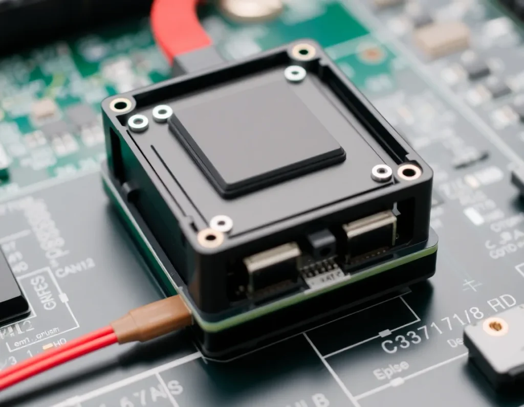
Un boîtier de module optique est l'enceinte standardisée en métal ou en métal et plastique qui contient et protège les composants essentiels d'un émetteur-récepteur optique. Considérez-le comme le châssis ou le squelette du module. À l'intérieur, des éléments délicats comme l'émetteur laser, le récepteur à photodiode, les circuits intégrés de pilotage et la circuiterie de commande sont montés sur une carte de circuit imprimé (PCB). Le boîtier fournit la structure rigide qui maintient ces composants dans un alignement précis, en particulier pour les sous-ensembles optiques qui doivent s'interfacer parfaitement avec le connecteur de fibre optique. Point crucial, le boîtier n'est pas une conception personnalisée pour chaque module ; il respecte des accords multi-sources (MSA) stricts qui définissent chacune de ses dimensions externes, son mécanisme de verrouillage du connecteur et la disposition de ses broches électriques. Cette standardisation est ce qui permet à un ingénieur réseau d'acheter un module QSFP28 d'un fabricant et de le brancher en toute confiance dans un commutateur d'un autre, sachant qu'il s'adaptera et fonctionnera. Le boîtier intègre également le port fibre duplex LC ou MPO à l'avant et le connecteur électrique de bord (les “ doigts dorés ”) à l'arrière. En substance, le boîtier est le pont physique et mécanique entre le monde fragile de l'optoélectronique et le monde robuste et standardisé du matériel réseau.
Fonctions essentielles et principes de conception des boîtiers de modules optiques
La conception d'un boîtier de module optique est un exercice d'équilibre complexe dicté par plusieurs fonctions non négociables. Chaque principe impacte directement la fiabilité et l'interopérabilité du module.
Interface mécanique et interopérabilité
La fonction première est de fournir une interface mécanique irréprochable avec la cage et le connecteur de l'équipement hôte. Les dimensions du boîtier, l'emplacement et la conception de son loquet, ainsi que le positionnement de ses trous de fixation doivent être exacts. Même une légère déviation peut empêcher l'insertion, provoquer un mauvais contact électrique ou endommager les broches sensibles du connecteur de l'hôte. La conception privilégie une sensation d'insertion et d'extraction fluide et franche tout en garantissant une connexion sécurisée et résistante aux vibrations.
Protection des composants et intégrité structurelle
Le boîtier agit comme un bouclier robuste contre les dommages physiques, la poussière et les contaminants. Il protège la carte PCB interne et les composants des contraintes de manipulation quotidiennes, des impacts accidentels et des forces mécaniques impliquées dans le raccordement et le débranchement des câbles à fibre optique. La structure doit être suffisamment rigide pour empêcher toute flexion, qui pourrait désaligner les composants optiques ou fissurer les joints de soudure, tout en étant conçue pour un assemblage efficace lors de la fabrication.
Chemin de conduction thermique
L'un de ses rôles les plus critiques est peut-être de servir de dissipateur thermique principal. Les lasers et processeurs de forte puissance génèrent une chaleur importante. Le boîtier est conçu pour évacuer cette chaleur des composants internes, généralement par contact direct avec le PCB et les puces clés, et la transférer vers la cage métallique plus grande du système hôte, qui dispose de sa propre solution de refroidissement. Toute la surface inférieure du boîtier fait souvent office de plaque de transfert thermique.
Confinement des interférences électromagnétiques (EMI)
Les signaux électriques à haute vitesse à l'intérieur d'un module peuvent rayonner du bruit électromagnétique, susceptible de perturber les équipements électroniques voisins. Inversement, le module doit être protégé des EMI externes. Le corps métallique du boîtier forme une cage de Faraday, confinant les émissions internes et protégeant les circuits sensibles des interférences externes. Les interstices et les joints sont méticuleusement conçus pour minimiser les fuites RF.
Matériaux clés et procédés de fabrication pour la durabilité et la performance
Le choix des matériaux et leur mode de mise en forme sont au cœur de la réalisation des principes de conception décrits ci-dessus. La performance, le coût et la fabricabilité sont tous des considérations essentielles.
Matériaux principaux
- Métaux (pour le corps principal) : L'alliage de zinc moulé sous pression est le matériau traditionnel et le plus courant. Il offre une excellente protection contre les EMI, une bonne conductivité thermique et une résistance élevée pour des formes complexes à un coût relativement faible. Pour les modules à plus haute performance, en particulier ceux générant plus de chaleur, des alliages de cuivre ou de l'aluminium sont parfois utilisés pour leur conductivité thermique supérieure, bien qu'ils puissent être plus coûteux et plus difficiles à mouler sous pression avec des détails fins. L'acier inoxydable est souvent utilisé pour le ressort de verrouillage et d'autres pièces mécaniques critiques en raison de sa durabilité et de ses propriétés élastiques.
- Plastiques (pour les façades et les composants) : Des plastiques techniques à haute température et haute résistance tels que le LCP (polymère à cristaux liquides) ou le PPS (sulfure de polyphénylène) sont utilisés pour la façade avant qui maintient les ports fibre. Ces matériaux peuvent résister à la chaleur du brasage lors de l'assemblage, assurent l'isolation électrique et permettent un moulage précis des interfaces délicates des adaptateurs fibre.
Procédés de fabrication
- Moulage sous pression : Il s'agit du procédé standard pour les boîtiers métalliques. Du zinc ou de l'aluminium en fusion est injecté sous haute pression dans un moule en acier de précision (coquille). Cela permet la production en série de pièces complexes, à forme nette, avec une bonne précision dimensionnelle, essentielle pour l'interopérabilité. Après le moulage, les pièces sont ébavurées, débarrassées des bavures et souvent plaquées (par exemple au nickel) pour la résistance à la corrosion et un meilleur contact de surface pour les performances EMI et thermiques.
- Usinage de précision : Utilisé pour les séries de prototypes, la production à très faible volume, ou pour créer des caractéristiques spécifiques à haute tolérance sur une pièce moulée sous pression. C'est plus coûteux et plus lent que le moulage sous pression.
- Injection Molding: Used for the plastic bezel and internal components. This process allows for high-volume, cost-effective production of parts with excellent detail, such as the snap-fits and guides for the fiber connector.
- Assembly and Welding: The final housing is often an assembly of several pieces. The metal top and bottom halves are typically laser-welded or fixed with screws. Laser welding creates a hermetic, continuous seam that maximizes EMI shielding and structural integrity without introducing additional materials like adhesives that could outgas or degrade.
Types and Form Factors: From SFP to QSFP-DD and Beyond
The evolution of data rates and port density has driven the development of a family of standardized form factors, each with its own distinct housing design. The form factor name essentially defines the housing’s size, shape, and electrical interface.
- SFP (Small Form-factor Pluggable): The workhorse of the industry for 1G/10G applications. Its compact, narrow housing is designed for high port density. Variations include SFP+ (enhanced for 10G/16G/25G) and SFP28 (for 25G). The housing is relatively simple but must still manage heat and EMI effectively.
- SFP-DD (Double Density): An evolution of SFP that doubles the port density by using two electrical lanes in the same width as a standard SFP. The housing is slightly deeper to accommodate the more complex internal layout and additional electrical contacts.
- QSFP (Quad Small Form-factor Pluggable): Significantly wider than SFP, designed to carry four lanes of data. This housing must manage substantially more heat and more complex internal routing. Its variants define generations: QSFP+ (40G), QSFP28 (100G), and QSFP56 (200G).
- QSFP-DD (Double Density): The leading high-density form factor for 400G and 800G. It builds on the QSFP width but adds a second row of electrical contacts (making it “double density”) to support eight high-speed electrical lanes. The housing design is a marvel of miniaturization and thermal engineering, as it packs immense processing power into a space not much larger than a QSFP28.
- OSFP (Octal Small Form-factor Pluggable): A slightly wider and deeper alternative to QSFP-DD for 800G applications. Its housing is designed from the outset for higher power dissipation, often incorporating a more robust thermal solution, such as an integrated heat sink for direct airflow.
- CFP (C Form-factor Pluggable): A much larger form factor used for early 100G and now for very high-power, long-reach applications like 400ZR coherent optics. Its large housing is necessary to accommodate complex electronics, larger lasers, and more sophisticated cooling solutions.
Each step in this progression represents a housing engineering challenge: packing more functionality into a constrained space while managing increased power and heat.
Thermal Management: How Housings Dissipate Heat for Reliability
As data rates skyrocket, the power consumption of optical modules has followed suit. A modern 800G module can easily dissipate 12-15 watts or more. If this heat is not effectively removed, component temperatures soar, leading to accelerated aging, increased bit error rates, wavelength drift in lasers, and ultimately, catastrophic failure. The boîtier de module optique is the central player in the thermal management system.
The thermal path begins inside the module. The hottest components, like the laser driver and DSP chip, are designed to transfer heat into the module’s PCB through thermal vias and pads. The PCB itself then conducts this heat to the metal baseplate of the housing, which is in direct mechanical contact with it. This baseplate is the workhorse of the thermal system. It spreads the heat across its entire surface area.
The next critical interface is between the housing’s baseplate and the host system’s cage. When the module is fully inserted, this metal-to-metal contact is the primary conduit for transferring heat out of the module. To optimize this, the housing baseplate is often machined flat and may even be lightly coated with a thermal interface material (TIM) like grease or a phase-change pad to fill microscopic air gaps that act as insulators.
The host cage is typically attached to a large thermal mass or heat sink on the system board, and often sits in the path of forced airflow from system fans. In some advanced designs, like the OSFP form factor, the housing itself may extend upward to present fins or a raised surface directly into the airflow, acting as an integrated heat sink. For the highest-power coherent modules, the housing may even be designed to interface with a cold plate for liquid cooling. Every aspect of the housing’s material, geometry, and surface finish is scrutinized for its impact on thermal impedance, making it a defining factor in the module’s performance envelope and reliability.
Mechanical and EMI Shielding: Protecting Sensitive Internal Components
Beyond managing heat, the boîtier de module optique serves as the first and most critical line of defense against physical and electromagnetic threats. The sensitive integrated circuits, lasers, and photodiodes inside a module are fragile and operate at high frequencies, making them vulnerable to damage from shock, vibration, and external interference. The housing’s mechanical integrity is therefore paramount. It is engineered to withstand the rigors of insertion and extraction, often thousands of cycles over its lifetime, without deforming. The latching mechanism, typically a bail or button-style design, is integrated into the housing and must provide secure retention in the host cage while allowing for smooth, tool-less removal. The housing also protects against dust and other contaminants, with tight tolerances and sometimes gasketing to prevent particulate ingress that could cloud optical interfaces or cause electrical shorts.
Perhaps an even more sophisticated role is electromagnetic interference (EMI) shielding. High-speed electrical signals inside the module can radiate energy, potentially disrupting nearby electronics. Conversely, external EMI from other system components can couple into the module and corrupt its high-speed data streams. The housing acts as a Faraday cage, enclosing the internal components in a continuous conductive shell. This is why materials like zinc die-cast alloy or steel with conductive plating are favored—they are not just structurally sound but also excellent conductors. The design ensures that when the module is fully inserted, the housing makes a 360-degree electrical contact with the metal host cage, creating an unbroken shielded enclosure. Critical openings, such as the port for the optical connector, are designed with careful attention to the gap size relative to the wavelength of the interference to prevent leakage. This comprehensive shielding is non-negotiable for meeting stringent regulatory emissions standards and ensuring the module functions reliably in the dense, noisy environment of a network switch or router.
Standards and Compliance: Ensuring Interoperability in Global Networks
The true power of optical modules lies in their universality. A module from one manufacturer must seamlessly plug and play in equipment from another, anywhere in the world. This interoperability is not accidental; it is enforced by a complex ecosystem of international standards that dictate nearly every aspect of the boîtier de module optique. Form factor definitions, managed by multi-source agreements (MSAs), are the most visible of these standards. Groups like the Small Form Factor Committee (SFF Committee) and ad-hoc MSA groups for QSFP, OSFP, and others publish detailed mechanical specifications. These documents precisely define the housing’s external dimensions, the position and shape of the latch, the connector port location, and even the labeling area. A deviation of a fraction of a millimeter could prevent a module from fitting into a host cage, so manufacturers adhere to these blueprints with extreme precision.
Compliance extends far beyond physical shape. The housing is central to meeting safety and environmental regulations. For instance, the housing material must often meet flammability ratings like UL 94 V-0. It must also ensure user safety by preventing accidental exposure to laser light, which is managed through the design of the port shutters and internal baffles. Electromagnetic compatibility (EMC) standards, such as those from the FCC (U.S.) and CE (EU), mandate the level of EMI shielding the completed module must achieve, directly validating the housing’s design and material conductivity. Furthermore, standards like Telcordia GR-468-CORE or IEC 62005 outline rigorous reliability testing for mechanical robustness, thermal cycling, and corrosion resistance—tests the housing must survive to prove the module’s worth for carrier-grade networks. This global framework of standards, while complex, is what allows data centers and telecom providers to build heterogeneous, scalable, and reliable networks with confidence.
The Future of Optical Module Housings: Trends and Innovations
As network demands push towards higher speeds, greater density, and lower power, the humble module housing is evolving to meet radical new challenges. The trend toward co-packaged optics (CPO) represents a potential paradigm shift. In CPO architectures, the optical engine is moved much closer to or even onto the same package as the switch ASIC, drastically reducing electrical path lengths. This could eventually lead to the disappearance of the traditional, pluggable module as we know it, replaced by onboard optical assemblies with specialized, integrated housings that focus on thermal and optical coupling rather than hot-swappability. However, pluggables will dominate for the foreseeable future, and their housings are adapting. For the next generation of 1.6T and 3.2T modules, power dissipation will exceed 30 watts, pushing air cooling to its limits. Future housings will increasingly be designed with liquid cooling in mind, featuring integrated microchannels or cold-plate interfaces as a standard option.
Material science is also driving innovation. To reduce weight and improve thermal conductivity, advanced composites and metal matrix composites (MMCs), like aluminum with embedded carbon fibers or diamond particles, are being explored. These materials can offer thermal performance superior to traditional aluminum alloys while being lighter. There is also a push for greater sustainability, leading to research into recyclable polymers and greener plating processes. On the design front, intelligent housings with embedded sensors are on the horizon. Tiny sensors for temperature, humidity, and even physical shock could be integrated into the housing structure, providing real-time telemetry for predictive health monitoring of the module and the broader system. Finally, as form factors like QSFP-DD and OSFP reach their electrical I/O limits, new housing designs will emerge to support even higher lane counts and novel internal architectures, all while maintaining backward compatibility or defining new standards for the next era of connectivity.
Résumé des points clés
The optical module housing is a deceptively complex component that is fundamental to the function and reliability of modern high-speed networks. It is far more than a simple metal shell. Its primary roles are multifaceted: it provides the critical mechanical structure and latching mechanism for secure, hot-swappable operation; it acts as the essential thermal path, conducting waste heat from internal components to the host system; and it serves as a comprehensive shield, protecting sensitive electronics from physical damage and electromagnetic interference. The choice of materials—typically zinc, aluminum, or advanced composites—is driven by the need for strength, thermal conductivity, and EMI suppression.
The housing’s design is almost entirely dictated by industry standards and multi-source agreements (MSAs), which ensure interoperability across vendors and form factors, from SFP to QSFP-DD and OSFP. Compliance with these mechanical, safety, and EMC standards is non-negotiable for global market acceptance. Looking ahead, the housing will continue to evolve to address the challenges of higher power densities, likely incorporating advanced liquid cooling interfaces, smarter materials, and even integrated sensor technology. As optical technology advances toward co-packaged optics and beyond, the housing’s role may transform, but its core mission of enabling reliable, high-performance connectivity will remain central to the architecture of our digital world.
Frequently Asked Questions (FAQ)
What is the main purpose of an optical module housing?
The housing serves three equally vital purposes. First, it provides the mechanical structure, including the latching mechanism, that allows the module to be securely inserted, retained, and hot-swapped in network equipment. Second, it acts as the primary heat sink, drawing thermal energy away from the high-power lasers and electronics inside and transferring it to the host system. Third, it forms a conductive Faraday cage that shields the module’s internal components from electromagnetic interference (EMI) and prevents the module itself from emitting disruptive signals.
Why are most optical module housings made of metal?
Metal, specifically die-cast zinc or aluminum alloys, is the material of choice because it uniquely combines several necessary properties. It is mechanically strong to withstand insertion cycles and physical stress, an excellent conductor of heat for thermal management, and an effective electrical conductor for EMI shielding. The manufacturing processes for metal, like die-casting and CNC machining, also allow for the creation of complex, high-precision shapes with the tight tolerances required by industry standards.
Can a housing be replaced if it gets damaged?
Generally, no. The optical module housing is not a field-replaceable part. It is hermetically sealed or precision-assembled in a cleanroom environment at the factory. The internal components are delicately aligned and bonded to the housing structure. Attempting to open or replace the housing would almost certainly destroy the module’s optical alignment and void any warranties. A damaged housing typically means the entire module must be replaced.
How do standards affect the design of a housing?
Standards and Multi-Source Agreements (MSAs) dictate virtually every external dimension of the housing. They specify the exact length, width, height, shape of the latch, position of the connector port, and even the electrical pin layout on the edge connector. This extreme standardization is what guarantees that a module from any vendor will fit and function correctly in a switch or router from any other vendor, enabling a competitive, interoperable market.
What is the difference between a housing and a cage?
The housing is the metal shell of the optical module itself. The cage (or “host cage”) is the receptacle soldered onto the system’s printed circuit board (PCB) that the module plugs into. The cage provides the electrical connector, guides the module into place, and features spring fingers that make electrical contact with the housing for EMI shielding. It also often includes features to aid in heat transfer from the housing to the board’s heat sink.
How will housings change for 800G and 1.6T modules?
Higher-speed modules consume more power, generating more heat. Housings for 800G, 1.6T, and beyond will place an even greater emphasis on thermal management. We will see more widespread adoption of designs with integrated heat-spreading fins (like OSFP), more sophisticated thermal interface materials, and direct integration with liquid cooling plates. The mechanical and EMI shielding requirements will also become more stringent due to the higher frequency electrical signals involved.