
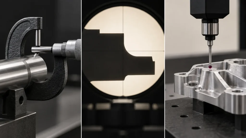
CMM, optical comparator, and manual inspection are not interchangeable checkpoints. Each method answers a different measurement question. A CMM is suited to three-dimensional relationships and GD&T. An optical comparator is efficient for visible profiles, radii, and small two-dimensional features. Manual tools are often the fastest way to verify straightforward dimensions, threads, and shop-floor adjustments. The right choice depends on the feature, tolerance, material, batch size, datum scheme, and the evidence a buyer needs to release the parts.
For custom CNC work, inspection should be planned with the drawing rather than selected after machining. A part can pass a caliper check and still fail a positional tolerance, a true profile, or a relationship between two faces. Conversely, sending every simple dimension to a CMM can add time without improving the decision. This guide compares the three approaches and shows how to build a practical inspection plan for a machined part.
Short answer: use manual tools for accessible, clearly defined dimensions; use an optical comparator for repeatable 2D profiles and delicate small features; use a CMM when the acceptance decision depends on datums, 3D geometry, GD&T, or a documented dimensional report. Most production plans combine them instead of choosing only one.
Start with the feature, not the machine name
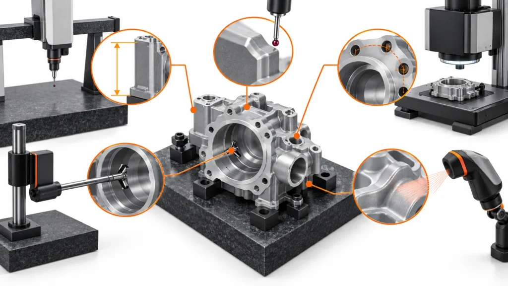 The inspection method should follow the characteristic being accepted. “The part was inspected” is not a sufficient quality statement unless the inspection plan identifies which features were measured, from which datums, with what method, and under what conditions.
This feature-first approach also keeps the inspection plan commercially realistic. A buyer may need a full report for critical characteristics but only a sampling check for routine dimensions. The method, sample size, and reporting depth should be agreed before production rather than assumed from the supplier’s equipment list.
What manual inspection does well—and where it stops
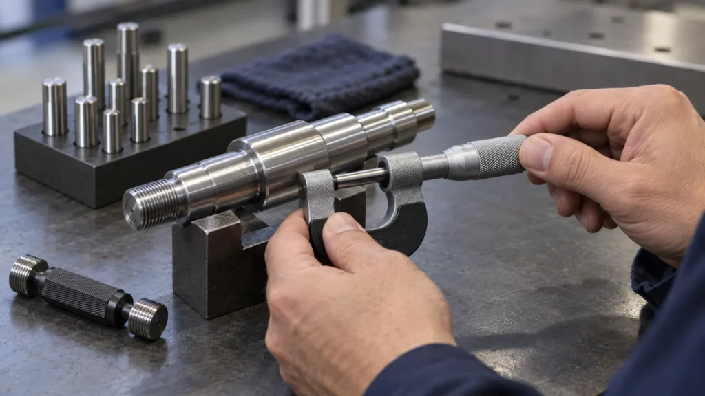 Manual inspection includes tools such as calipers, micrometers, pin gauges, thread gauges, height gauges, indicators, radius gauges, and surface plates. These tools remain valuable because they are quick, flexible, and available close to the machine. An operator can check a bore after a tool adjustment, confirm a shaft diameter before removing the part, or verify a thread with a go/no-go gauge without waiting for a laboratory queue.
Manual inspection is a strong choice when:
Manual inspection includes tools such as calipers, micrometers, pin gauges, thread gauges, height gauges, indicators, radius gauges, and surface plates. These tools remain valuable because they are quick, flexible, and available close to the machine. An operator can check a bore after a tool adjustment, confirm a shaft diameter before removing the part, or verify a thread with a go/no-go gauge without waiting for a laboratory queue.
Manual inspection is a strong choice when:
It becomes less suitable when the result depends heavily on operator technique, contact force, part temperature, alignment, or interpretation. A caliper reading cannot by itself prove a position tolerance. A thread plug can verify functional engagement, but it does not replace a complete dimensional evaluation when the drawing controls pitch diameter, location, perpendicularity, or a sealing interface. Soft plastics, thin walls, and flexible sheet-like features can also deform under contact pressure.
Manual tools are therefore best treated as part of a layered control plan. They provide rapid feedback during setup and production, while a more structured method is reserved for features where measurement uncertainty or geometric relationships could change the release decision.
When an optical comparator is the better choice
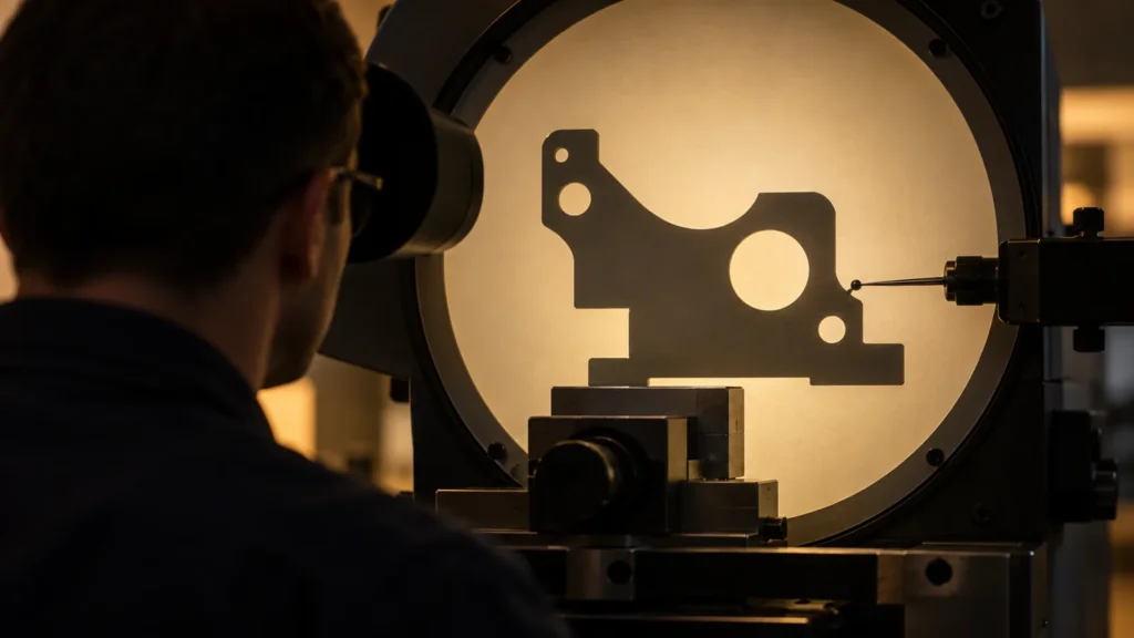 An optical comparator projects a magnified silhouette or image of a feature so the inspector can evaluate a profile, radius, angle, edge break, or other visible two-dimensional characteristic. Modern vision systems may add digital edge detection and programmed measurement, but the underlying advantage is similar: the part can be evaluated without pressing a probe against a delicate feature.
Optical inspection is often useful for small parts, thin sections, stamped-like profiles, slots, radii, intersecting lines, and features where a contact probe could bend or mark the surface. It can also be efficient when many similar 2D characteristics must be checked repeatedly. For a flat profile with a clearly defined orientation, the result may be easier to explain to a buyer than a collection of manual readings.
There are boundaries. A projected outline does not automatically establish the full 3D datum structure. It may not verify the depth of a pocket, the coaxiality of separated bores, or the relationship between features on different faces. Lighting, edge condition, burrs, coating, transparency, and the selected contour can influence the result. For this reason, the inspection plan should specify whether the requirement is a silhouette, a measured edge, a profile tolerance, or a functional boundary.
Optical comparison should not be described as universally more accurate than manual inspection or a CMM. Its value is task fit: non-contact measurement, repeatable 2D evaluation, and efficient handling of features that are difficult to touch reliably. For a deeper discussion of how the inspection method connects to the drawing, link this section to the site’s guide des tolérances d'usinage CNC.
An optical comparator projects a magnified silhouette or image of a feature so the inspector can evaluate a profile, radius, angle, edge break, or other visible two-dimensional characteristic. Modern vision systems may add digital edge detection and programmed measurement, but the underlying advantage is similar: the part can be evaluated without pressing a probe against a delicate feature.
Optical inspection is often useful for small parts, thin sections, stamped-like profiles, slots, radii, intersecting lines, and features where a contact probe could bend or mark the surface. It can also be efficient when many similar 2D characteristics must be checked repeatedly. For a flat profile with a clearly defined orientation, the result may be easier to explain to a buyer than a collection of manual readings.
There are boundaries. A projected outline does not automatically establish the full 3D datum structure. It may not verify the depth of a pocket, the coaxiality of separated bores, or the relationship between features on different faces. Lighting, edge condition, burrs, coating, transparency, and the selected contour can influence the result. For this reason, the inspection plan should specify whether the requirement is a silhouette, a measured edge, a profile tolerance, or a functional boundary.
Optical comparison should not be described as universally more accurate than manual inspection or a CMM. Its value is task fit: non-contact measurement, repeatable 2D evaluation, and efficient handling of features that are difficult to touch reliably. For a deeper discussion of how the inspection method connects to the drawing, link this section to the site’s guide des tolérances d'usinage CNC.
When a CMM earns its place in the inspection plan
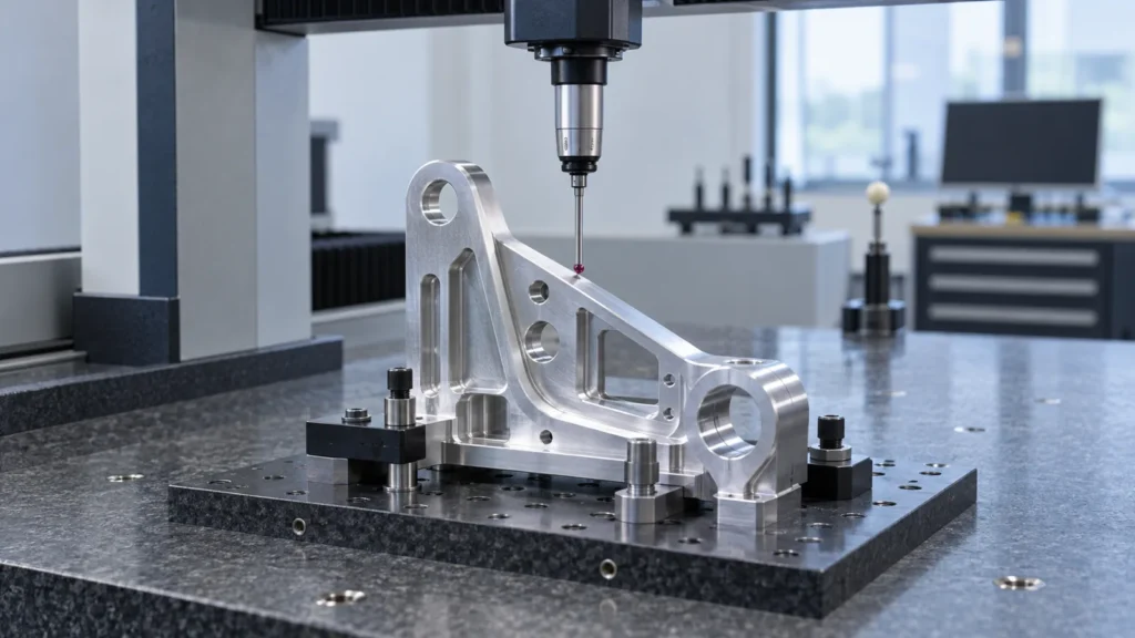 A coordinate measuring machine establishes points in a coordinate system and evaluates them against nominal geometry. Its main advantage is not simply a small number on an accuracy specification. It is the ability to measure relationships: a hole pattern relative to datums, a face’s orientation, the location of a bore, or a complex profile across several surfaces.
A CMM is especially appropriate when a drawing includes:
A coordinate measuring machine establishes points in a coordinate system and evaluates them against nominal geometry. Its main advantage is not simply a small number on an accuracy specification. It is the ability to measure relationships: a hole pattern relative to datums, a face’s orientation, the location of a bore, or a complex profile across several surfaces.
A CMM is especially appropriate when a drawing includes:
The CMM program still needs engineering judgment. The report should identify the alignment, datums, feature definitions, measured points, evaluation rules, temperature assumptions, and drawing revision. A colorful deviation map without that context may look impressive but leave the buyer unable to determine what was actually accepted. A supplier should also distinguish between a report for a first article, a report for selected critical features, and a production sampling record.
CMM inspection is not automatically necessary for every part. If the only requirement is a simple outside diameter, a calibrated micrometer may provide a faster and more appropriate check. If the part is flexible, clamping and support can affect the result. If the measured feature is contaminated with chips, burrs, or residue, the machine may produce repeatable data for a poorly prepared part. Measurement planning and part preparation remain part of quality control.
A practical combination for prototypes and production batches
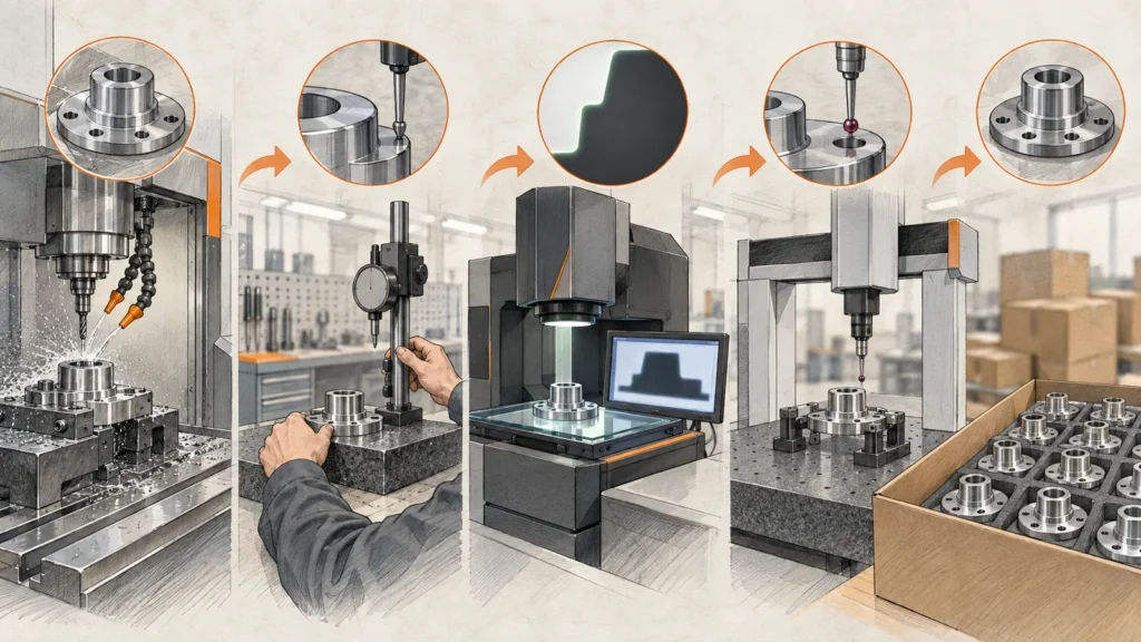 Most CNC projects benefit from assigning each feature to the simplest method that can defend the acceptance decision. A typical plan might use manual tools for in-process dimensions, an optical system for a delicate profile, and a CMM for the datum-related characteristics and first-article report.
The inspection plan should also reflect the material and process. Aluminum, stainless steel, titanium, engineering plastics, and copper alloys can respond differently to cutting heat, clamping, burr formation, and temperature changes. A method that is convenient for a rigid steel bracket may be unsuitable for a thin polymer cover. When discussing the material choice, the relevant guide des matériaux d'usinage CNC can provide the broader engineering context.
For supplier evaluation, ask what the quality process can demonstrate for your specific drawing rather than asking only how many instruments are in the factory. The company’s quality capabilities page can be used as a starting point, but the final inspection scope, report format, sampling rule, and acceptance criteria should still be confirmed for the individual order.
Questions to settle before requesting inspection
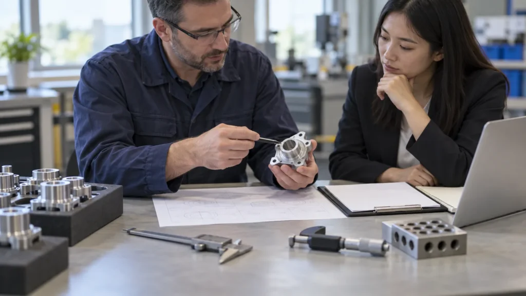 Clear inputs prevent both under-inspection and unnecessary inspection cost. Before sending an RFQ or approving a first article, define:
The answers turn “please inspect carefully” into a quality plan that two organizations can interpret the same way. For a general overview of how these checkpoints fit into production, see the parent article on CNC machining quality control.
Frequently asked questions
Is a CMM always better than manual inspection?
No. A CMM is better for many 3D relationships and GD&T evaluations, but a calibrated micrometer, pin gauge, or thread gauge may be faster and more suitable for a simple accessible feature.
Can an optical comparator replace a CMM?
Only for the characteristics it can measure and the datum conditions it can establish. It is useful for 2D profiles and delicate features, but it does not automatically verify every 3D relationship on a CNC part.
Should every dimension appear on the inspection report?
That depends on the drawing, customer requirement, first-article scope, and agreed quality plan. The report scope should be defined before production; a selected-characteristic report should not be presented as a complete inspection of every drawing requirement.
What should a buyer send with the CAD file?
Send the controlled drawing, revision, units, material and finish requirements, critical features, GD&T interpretation, quantity, sampling or report expectations, and any special test or traceability requirements. CAD geometry alone does not define every acceptance condition.
Bottom line: choose the measurement method according to the feature and the decision it must support. Manual inspection gives fast process feedback, optical inspection handles repeatable 2D and delicate profiles, and CMM inspection supports complex 3D relationships and documented dimensional evidence. A well-designed combination produces clearer release decisions than relying on one instrument for every characteristic.