
Casting datum targets for machining are most useful when the foundry, CNC shop, and inspector can all identify the same physical references on the delivered blank. A datum plan should connect the casting’s functional geometry to the later machined features without assuming that every as-cast surface is stable, accessible, or dimensionally uniform. The handoff needs to show what is controlled at each stage and which party owns each requirement.
This is a drawing-coordination guide, not a method for selecting foundry tooling or setting universal casting allowances. Alloy, process, part size, draft, stock, and the machining sequence all affect what references are practical.
Separate the casting reference from the finished-part datum
A finished component may locate from machined bores, pads, or mounting faces that do not yet exist on the raw casting. The blank still needs a repeatable way to be oriented and supported for the first machining operations. State whether that first setup references cast pads, temporary targets, a fixture profile, or another agreed feature.
Do not let a temporary rough reference silently become the finished datum scheme. The drawing should distinguish setup references used to establish initial cuts from the datum features that control final assembly and inspection. This prevents a convenient casting surface from unintentionally dictating the location of a functional bore or interface.
Make targets physical and inspectable
Casting datum targets for machining should be located where the blank provides enough material and the fixture can reach them without rocking or excessive clamp force. Targets may use discrete contact areas rather than an entire rough face, but their size, position, and use must be clear to the people building the fixture and checking the blank.
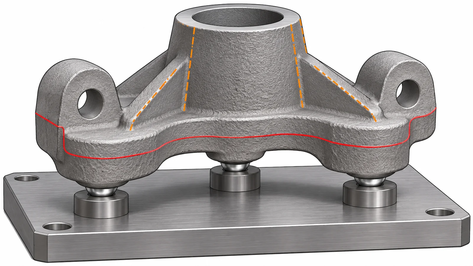
Consider draft, parting lines, gates, risers, flash, and local surface variation. A target placed on a drafted or interrupted area may not seat consistently. If the casting surface is unsuitable, the drawing and process plan can identify sacrificial pads or a controlled fixture interface, provided the design and foundry agree on the feature and its removal or retention.
Coordinate stock and first-operation cuts
Before release, compare the casting model and machining model around every surface that will be cut. The stock envelope must leave enough material for cleanup while preserving wall thickness and the final feature position. Allowance is process- and geometry-dependent; a single blanket value may not cover draft, distortion, or local shifts across a large or asymmetric casting.
Mark critical machining regions and indicate which rough surfaces can remain untouched. First-operation cuts should create stable, usable references for later setups. If a feature is likely to move as stock is removed, sequence roughing and finishing so the part can relax or be re-supported before final dimensions are established.
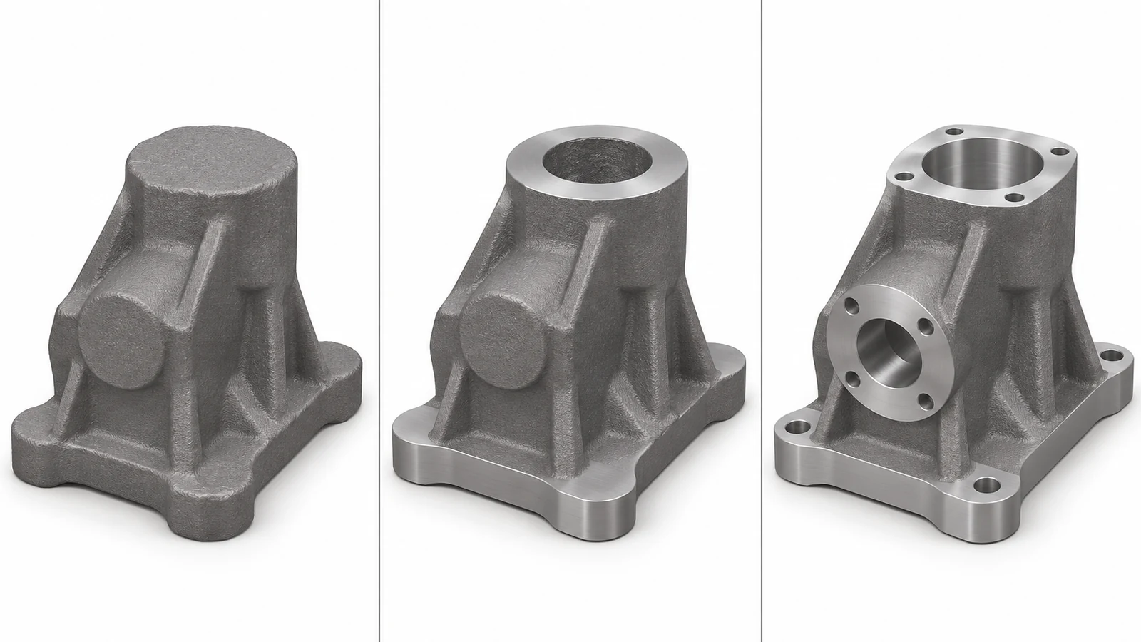
For the machining stage, relate the handoff to the actual scope of CNC machining versus investment casting. The casting process creates the near-net blank; the CNC plan controls the specified finished interfaces and does not replace foundry acceptance requirements.
Keep inspection ownership explicit
Inspection documents should say whether a requirement applies to the raw casting, after initial machining, or on the finished part. Those are different states. A cast envelope check may use targets that disappear in later operations, while final inspection should use the released datum reference frame and the stated drawing requirements.
When the part is large, flexible, or asymmetric, define support and clamping conditions for measurement. Record the target points or datum simulators, and state how non-machined surfaces are evaluated. If foundry and machining suppliers each inspect a portion of the process, the purchase documents should identify the handoff records and nonconformance path.
Handoff checklist for a cast blank
- Identify rough setup references separately from finished-part datums.
- Show target locations that are accessible, stable, and not interrupted by draft or parting features.
- Coordinate the stock envelope and cleanup expectations around critical walls and interfaces.
- State which requirements apply to raw, semi-finished, and final part conditions.
- Agree who verifies casting condition, machining stock, datum transfer, and final dimensions.
Clear casting datum targets for machining turn a vague “machine from casting” instruction into a repeatable supplier handoff. The drawing, fixture plan, and inspection record should all describe the same references and the same stage of the part’s manufacturing route.