
Einführung in das Drahterodieren: Präzisionsschneiden für komplexe Teile
In der Welt der fortschrittlichen Fertigung, in der Komplexität auf kompromisslose Präzision trifft, Drahterosionsdienstleistungen steht als Eckpfeilertechnologie. Auch bekannt als Wire Electrical Discharge Machining (Wire EDM), ist dieses Verfahren die definitive Lösung für die Herstellung komplexer Teile, die mit konventioneller Bearbeitung unmöglich, unpraktisch oder unerschwinglich teuer herzustellen wären. Es überwindet die Grenzen physischer Schneidwerkzeuge und nutzt kontrollierte elektrische Funken, um Material mit erstaunlicher Genauigkeit abzutragen. Für Ingenieure und Konstrukteure, die mit gehärteten Stählen, exotischen Legierungen oder Komponenten mit filigranen Merkmalen und engen Toleranzen arbeiten, ist das Drahterodieren nicht nur eine Option – es ist eine unverzichtbare Fähigkeit, die die Lücke zwischen ehrgeizigem Design und fertigbarer Realität schließt. Dieser Leitfaden befasst sich mit der Wissenschaft, den Vorteilen und den praktischen Anwendungen dieser transformativen Technologie.
Was ist Wire EDM? Die Wissenschaft des elektrischen Entladungsbearbeitens erklärt
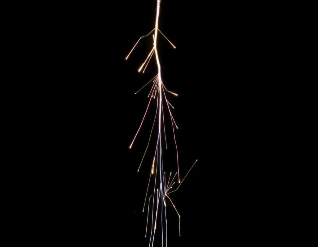
Im Kern ist Wire EDM ein thermoelektrisches Bearbeitungsverfahren. Es trägt Material durch eine Reihe schneller, kontrollierter elektrischer Entladungen (Funken) zwischen einer dünnen, präzise geführten Drahtelektrode und dem leitfähigen Werkstück ab. Die beiden stehen niemals in physischem Kontakt, wodurch mechanische Spannungen und Werkzeugverschleiß, die mit Fräsen oder Drehen verbunden sind, eliminiert werden.
Der Prozess findet in einem Becken mit deionisiertem Wasser statt, das einen kritischen doppelten Zweck erfüllt. Erstens wirkt es als dielektrische Flüssigkeit, die den Draht und das Werkstück isoliert, bis die Spannung einen Schwellenwert erreicht, der hoch genug ist, um einen winzigen Pfad zu ionisieren und einen Funken zu erzeugen. Zweitens kollabiert die Flüssigkeit nach jedem Funken heftig und spült mikroskopische Partikel des abgetragenen Materials weg und verhindert, dass sie wieder an die Oberfläche anschweißen.
Eine Spule mit Draht, typischerweise aus Messing oder geschichtetem Kupfer, wird kontinuierlich zwischen oberen und unteren Führungen zugeführt. Diese Führungen, gesteuert durch ein CNC-System, bewegen sich unabhängig voneinander entlang der X- und Y-Achsen, wodurch die Maschine komplexe zweidimensionale Profile und konische Formen durch dicke Materialblöcke schneiden kann. Während der Draht läuft, wird er ständig erneuert, was eine frische, gleichbleibende Elektrode gewährleistet. Jeder Funke verdampft einen winzigen Krater im Werkstück, und die kumulative Wirkung von Tausenden von Funken pro Sekunde führt zu einem glatten, präzisen Schnitt. Die “Schnittfuge” oder Breite des Schnitts wird durch den Drahtdurchmesser plus den Funkenabstand bestimmt, der typischerweise zwischen 0,001” und 0,012” liegt, was die Erstellung extrem feiner Merkmale und scharfer Innenkanten ermöglicht.
Hauptvorteile und Nutzen der Verwendung von Drahterodieren-Dienstleistungen
Der einzigartige berührungslose, funkenbasierte Mechanismus des Drahterodierens verleiht eine Reihe von Vorteilen, die es für bestimmte Fertigungsherausforderungen unverzichtbar machen.
- Extreme Präzision und Genauigkeit: Drahterodiermaschinen sind in der Lage, Toleranzen innerhalb von ±0,0001 Zoll (0,0025 mm) einzuhalten. Diese Genauigkeit ist unabhängig von der Härte des Materials konstant, was es ideal für die Herstellung von Werkzeugen, Lehren und kritischen Luft- und Raumfahrtkomponenten macht.
- Fähigkeit zur Bearbeitung gehärteter Materialien: Da das Verfahren nicht auf Schnittkraft angewiesen ist, eignet es sich hervorragend für die Bearbeitung von gehärteten Werkzeugstählen, Hartmetallen und exotischen Legierungen in ihrem fertigen Zustand. Dies eliminiert die Verzerrungsrisiken, die mit dem Härten eines Teils nach der Schruppbearbeitung verbunden sind.
- Komplexe Geometrie und feine Merkmale: The thin, continuously moving wire can cut intricate profiles, micro-sized holes, and parts with exceptionally thin walls. It produces sharp inside corners that are impossible to achieve with an end mill, which has a finite radius.
- Überlegene Oberflächengüte: The erosion process inherently leaves a fine, matte surface finish, often in the range of 16 to 64 microinches Ra, directly from the machine. This often eliminates the need for secondary finishing operations for many applications.
- Burr-Free Production: The thermoelectric nature of the process means no mechanical burrs are generated. Parts come off the machine clean, saving time and cost on deburring, especially for complex internal geometries.
- Minimal Material Stress: With no direct contact or cutting forces, there is no chance of inducing mechanical stress, distortion, or micro-cracks into the workpiece, which is crucial for fragile or high-integrity components.
Wire EDM vs. Other Manufacturing Processes: When to Choose Wire Erosion
Selecting the right manufacturing process is a balance of geometry, material, tolerance, and cost. Here’s how wire EDM compares to other common methods and when it becomes the optimal choice.
Wire EDM vs. CNC Milling
CNC milling uses a rotating cutting tool to remove material and is exceptionally versatile for 3D contours, pockets, and threads. Choose milling for faster material removal on softer materials, complex 3D shapes, and when threaded holes or tapped features are required. Switch to wire erosion services when dealing with hardened materials (above 45 HRC), when you require sharp internal corners, or when the part geometry involves deep, narrow slots that would break a small end mill.
Wire EDM vs. Laser Cutting
Laser cutting is extremely fast for profiling sheet metal and can cut non-conductive materials. It is the go-to for high-volume 2D parts from sheet stock. However, lasers generate a heat-affected zone (HAZ) and taper, especially in thicker materials. Wire EDM produces no HAZ, offers superior accuracy and surface finish through greater thicknesses (commonly up to 150mm and beyond), and creates perfectly vertical walls or controlled tapers as programmed.
Wire EDM vs. Photo Chemical Etching
Photo etching is excellent for producing extremely thin, flat, burr-free parts with complex through-features, like stencils or lead frames. However, it is limited in material thickness (generally under 2mm) and cannot produce blind features or 3D forms. As noted in the knowledge base, wire erosion is the necessary alternative “for those metals whose chemical composition make photo etching impossible,” and for any part where depth and true 3D profiling are required.
The Decision Rule: Strongly consider wire EDM if your project involves a conductive material that is very hard, requires ultra-precise 2D/tapered profiles, has delicate features prone to tool deflection, or must be machined burr-free and stress-free after heat treatment.
Materials Compatible with Wire Erosion: From Aluminum to Exotic Alloys
A primary strength of wire EDM is its remarkable material versatility. Any electrically conductive material can be machined, with the process being particularly advantageous for those that are difficult for traditional methods.
- Tool Steels & Die Steels: This is a classic application. D2, A2, H13, and other hardened tool steels (often at 58-62 HRC) are machined with ease to create punches, dies, and mold inserts.
- Stainless Steels: All grades, including 303, 304, 316, and 17-4 PH, are perfectly suited. Wire EDM avoids the work-hardening issues that can plague milling of certain stainless grades.
- Aluminum and Alloys: Readily machined, though settings are adjusted for higher conductivity. Ideal for precision aerospace or prototype components.
- Copper, Brass, and Phosphor Bronze: These conductive materials are easily processed, making wire EDM suitable for electrical components and intricate decorative pieces.
- Exotic & High-Temperature Alloys: The process excels with materials like Inconel, Hastelloy, titanium, and tungsten carbide. Their toughness and hardness, which wear down conventional tools rapidly, pose no problem for the non-contact EDM spark.
- Other Conductive Materials: This includes molybdenum, nickel silver, and even specialized graphites. The key determinant is electrical conductivity, not mechanical hardness.
It is important to note that while all these materials are compatible, the specific EDM parameters—wire type, feed rate, voltage, and flush pressure—are meticulously optimized for each material type and thickness to achieve the desired cutting speed, surface finish, and dimensional accuracy. This expertise is a critical value provided by professional wire erosion service providers.
The Wire EDM Process: A Step-by-Step Guide from Design to Finished Part
Understanding the workflow of a wire EDM project demystifies how complex parts are created with such high precision. The journey from a digital concept to a physical component is a collaborative and methodical process, typically managed by your chosen Drahterosionsdienstleistungen provider.
Step 1: Design and File Preparation
It all begins with a 2D CAD drawing or a 3D model. The most critical information for the wire EDM machine is the precise cutting path. Engineers convert the design into machine code (typically G-code), defining the wire’s trajectory. At this stage, factors like the kerf (the width of material removed by the wire) are automatically compensated for in the toolpath to ensure final dimensions are exact.
Step 2: Material Setup and Workpiece Mounting
The selected conductive material is securely clamped onto the machine’s worktable. Accurate alignment is crucial. For internal cuts that don’t start at an edge, a starter hole must be pre-drilled, often using a dedicated EDM hole-drilling machine. The thin brass or coated wire is then threaded through this hole and connected to the spooling mechanism.
Step 3: Dielectric Fluid System Activation
The work area is flooded with deionized water, which serves as the dielectric fluid. This fluid electrically insulates the wire and workpiece until the voltage is high enough to create a spark. It also rapidly cools the vaporized material, flushing away microscopic debris from the cut zone to ensure a clean, consistent spark and prevent short-circuiting.
Step 4: The Cutting Operation
With the system energized, a controlled electrical discharge sparks across the small gap between the wire and the workpiece. Each spark generates intense heat, locally melting and vaporizing a tiny particle of the material. The wire, which is constantly fed from a spool to present a fresh, unworn section, moves along the programmed path. The upper and lower wire guides can move independently, allowing for the creation of tapered shapes and complex geometries in the X, Y, U, and V axes.
Step 5: Completion and Post-Processing
Once the cut is complete, the wire is retracted, the dielectric fluid is drained, and the finished part is removed from the remnant material (the “slug”). Depending on the application requirements, the part may then move to post-processing, such as deburring (though wire EDM typically leaves minimal burrs), surface finishing, or heat treatment.
Design Considerations and Best Practices for Wire EDM Parts
Designing with wire EDM’s unique capabilities in mind unlocks its full potential for cost-effectiveness and precision. Adhering to a few key principles ensures manufacturability and optimal results.
Internal Corners and Radii
Wire EDM can produce exceptionally sharp internal corners, a significant advantage over milling. However, it’s important to remember that the wire is a physical object with a diameter. An internal corner will always have a minimum radius slightly larger than the wire’s radius plus the spark gap. Specifying a small, achievable corner radius (e.g., 0.1mm) is better than demanding a perfectly sharp corner, which is physically impossible.
Material Thickness and Layering
While wire EDM can cut very thick materials (often over 150mm), thinner parts pose a challenge as they can warp or vibrate. For very thin sheets, it is often more economical and stable to layer multiple sheets of the same material, bolt them together, and cut them as a single block—a process known as stack cutting.
Start Holes and Unattended Features
Any internal cutout requires a start hole for the wire to thread through. The location and size of these holes should be considered in the design phase. Furthermore, “unattached” features that will fall out when cut must be accounted for; the machine may need to pause to allow an operator to secure them before continuing.
Tolerances and Surface Finish Expectations
Wire EDM is renowned for holding tight tolerances, often within ±0.005 mm for high-precision work. However, specifying tolerances that are tighter than necessary increases cost and time. Similarly, the as-cut surface finish is typically smooth but matte, ranging from 16 to 64 microinches (Ra). If a finer finish is required, it should be noted as a post-processing step.
Minimizing Cut Time and Cost
Reducing the total linear length of cutting directly reduces cost. Designers should aim for efficient nesting of parts within the raw material and consider simplifying non-critical contours. The choice of material and its thickness also significantly impacts cutting speed and, consequently, price.
Surface Finishes and Post-Processing Options for Wire Eroded Components
The standard finish from wire EDM is a uniform, matte surface free of tool marks, often suitable for functional parts without further work. However, many applications demand enhanced properties, which are achieved through various post-processing techniques.
Standard Finishes
- As-Cut (Standard Finish): The default state after EDM. It has a consistent texture but may exhibit fine recast layers and microscopic pitting from the sparks. It is ideal for non-wearing internal components or where further finishing is not justified.
- Kugelstrahlen: Uses fine abrasive media propelled by air to clean the surface and create a uniform, satin-matte appearance. It can lightly improve surface texture and remove minor discoloration.
- Tumbling/Vibratory Finishing: A batch process where parts are placed in a vibrating tub with abrasive media. It is excellent for radiusing edges, removing microscopic burrs, and producing a smooth, uniform finish on all exposed surfaces.
Enhanced and Protective Coatings
- Eloxieren (Typ II & III): Primarily for aluminum. Type II provides corrosion resistance and color for identification or aesthetics. Type III (Hardcoat) adds a thick, wear-resistant ceramic layer, invaluable for moving parts and tools.
- Passivierung: A chemical bath for stainless steel that removes free iron from the surface and promotes the formation of a passive chromium oxide layer, dramatically enhancing corrosion resistance without altering dimensions.
- Electroless Nickel Plating: Deposits a uniform, hard, and highly corrosion-resistant nickel-phosphorus alloy coating. It provides excellent lubricity and wear resistance, even on complex geometries.
- Pulverbeschichtung: Provides a thick, durable, and decorative polymer coating. It offers superior corrosion protection and a wide range of colors for consumer-facing or harsh-environment components.
Spezialisierte Oberflächenbehandlungen
- Elektropolieren: An electrochemical process that removes a thin surface layer, smoothing micro-peaks and leaving a bright, shiny, and more corrosion-resistant finish. Common for medical and food-grade stainless steel components.
- PTFE-Impregnated Hard Anodize: A hardcoat anodize infused with Teflon, creating a self-lubricating, dry-contact surface with exceptional wear and corrosion resistance for aluminum parts in dynamic assemblies.
Industries and Applications: Where Wire Erosion Services Excel
The unique capabilities of wire EDM make it indispensable across a spectrum of high-tech and demanding industries where precision, complex geometry, and hard materials are the norm.
Luft- und Raumfahrt sowie Verteidigung
This sector relies on wire EDM for manufacturing mission-critical components from exotic, high-strength alloys like Inconel and titanium. Applications include turbine blades, fuel system components, structural brackets with lightening pockets, and flight control parts. The process’s ability to produce stress-free cuts in heat-treated materials is paramount here.
Medical and Surgical Device Manufacturing
Precision is literally a matter of life and death. Wire EDM is used to create intricate bone screws, orthopedic implants (like knee and hip replacements), surgical instrument jaws, and components for minimally invasive devices. The biocompatible materials used, such as specific grades of stainless steel and titanium, are machined flawlessly to meet stringent FDA and ISO 13485 standards.
Tool and Die Making
Wire erosion is a cornerstone technology for producing stamping dies, extrusion dies, and injection molds. It can create complex punch and die shapes with exceptional accuracy and fine surface finishes, often as the final machining step on hardened tool steel. This eliminates distortion that could occur if the tool were machined before heat treatment.
Automotive and Motorsports
From prototyping to production, wire EDM creates gears, transmission components, sensor parts, and lightweight structural elements. In high-performance motorsports, it is used to machine one-off parts from the toughest materials, where weight savings and absolute reliability are critical.
Electronics and Semiconductor Manufacturing
The process fabricates precise components for connectors, micro-electromechanical systems (MEMS), and fixtures used in semiconductor production. Its ability to cut delicate, thin-walled features in conductive materials like copper, brass, and beryllium copper is highly valued.
General Engineering and Prototyping
For any project requiring a one-off precision part, a complex prototype, or a low-volume production run in a hard material, wire EDM offers a fast and cost-effective solution. It enables engineers to test designs with real-world materials without the high cost of dedicated hard tooling.