
A taper can be present in the program and still miss the intended angle on the part. The discrepancy may come from more than the commanded geometry: wire lag, flushing conditions, material thickness, path direction, setup alignment, and how the angle is measured can all affect the result. Treating every miss as a simple offset problem risks correcting the wrong variable and moving the error somewhere else on the part.
This diagnostic guide is for engineers reviewing a wire EDM taper feature. It separates the programmed angle from the physical cut and the inspection result, then lays out a practical order for narrowing the cause. It does not promise a universal correction value; the machine, wire, material, thickness, cut strategy, and measurement method determine what must be verified.
Define which angle is missing
First clarify the drawing requirement. Is the feature defined by an angle relative to a datum plane, a top-to-bottom displacement over a stated height, or a tapered profile that must match a mating component? These are related but not interchangeable inspection tasks. A reported angle without its reference direction, measurement location, and datum basis is not enough to identify the error.
For a tapered wall, record both the intended geometry and the measured condition. Where practical, capture the top and bottom profiles and the separation between them over the relevant height. If the part has multiple tapered faces or a changing profile, identify which section is being measured. A single spot measurement can miss twist, bow, or a local transition near the start or end of the cut.
Confirm whether the drawing specifies the angle as an included angle or a one-sided angle. Also verify the unit system and datum references. A correctly cut feature can appear wrong if the measurement is taken from a different reference face or if the comparison uses a different convention.
Separate commanded taper from cut geometry
Wire EDM creates a kerf through electrical erosion. For a tapered cut, the wire is tilted or guided so its position changes through the workpiece thickness. The machine command describes the intended wire path, but the wire is not a perfectly rigid line under every cutting condition. The actual profile can be influenced by wire deflection, discharge conditions, flushing, material response, and the strategy used for roughing and finishing.
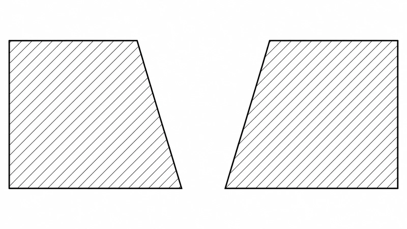
A feature that is accurate at the top but drifts at the bottom may point to a different issue than one that has the correct overall angle but a poor local surface. Similarly, an error that changes with cut direction may indicate path or flushing effects, while a consistent offset across several features may indicate setup, calibration, or datum alignment. These are hypotheses to test—not automatic diagnoses.
Review the complete operation: start hole or entry, lead-in, corner transitions, main taper, lead-out, and any skim cuts. A short transition may not settle into the same condition as the long steady portion of the cut. For the site’s process context, see the Wire EDM capability page; the exact feature should still be evaluated against its drawing and inspection plan.
Use the pattern of error as evidence
| Observed pattern | Possible area to investigate | Evidence to collect |
|---|---|---|
| Angle changes from top to bottom more than expected | Wire response, thickness, cut condition, or programmed geometry | Top/bottom profile, thickness, and operation settings |
| One direction cuts differently from the reverse direction | Path direction, flushing access, or entry/exit behavior | Compare matched features with opposite travel direction where feasible |
| Most features share a similar angular offset | Setup alignment, datum transfer, or machine reference | Setup records and an independent reference measurement |
| Only corners or short segments are out | Transition path, corner compensation, or local wire response | Measure at multiple positions, not only the straight section |
| Program checks pass but inspection disagrees | Measurement convention, fixture, or datum interpretation | Inspection setup, probe/fixture alignment, and drawing basis |
The table is a starting framework, not a substitute for the machine maker’s process guidance. Change one plausible cause at a time and retain the original setup data. If the result is corrected by changing a parameter, confirm that the correction does not create a new error on another face or alter the required profile.
Check setup and measurement before offsetting
Recheck workpiece orientation, clamping, reference faces, and the relation between the part datum and machine coordinates. A small setup rotation can appear as an angle error, particularly when a feature is measured over a limited span. If the workpiece can move or distort under clamping, compare the condition while held and after release where the inspection plan allows.
Then examine the measurement method. A CMM, optical comparator, height-based calculation, or dedicated fixture may report different results if the datum alignment or edge-detection method differs. Confirm the measurement points, surface filtering, and whether the top and bottom edges are clean enough to define a stable profile. Repeated measurements by the same method help distinguish a real process shift from setup variation.
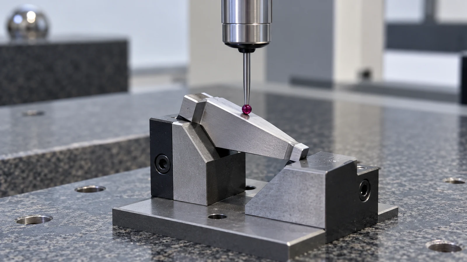
Do not use an arbitrary hand measurement as the sole acceptance basis for a critical taper. If the tolerance is tight or the surface is difficult to access, the inspection plan should specify a suitable method and datum alignment. Measurement uncertainty matters: a small reported deviation may not be meaningful if it is near the uncertainty of the measurement setup.
Make one controlled correction
Once the evidence points to a likely cause, plan a limited test. Keep the material, thickness, wire, fixture, and inspection procedure stable while changing the parameter or path element under review. Document the original command, the measured top and bottom geometry, and the actual adjustment. Avoid stacking several changes in one trial; the result will not show which change mattered.
Evaluate the full feature, not only the point that failed. A taper correction can affect straightness, surface condition, corner geometry, and the opposite face. If the part mates with another component, check the functional fit under the specified datum relationship. A visually improved wall is not necessarily a conforming feature.
For repeat work, preserve the verified setup and process notes with the part revision. When the drawing, stock thickness, material, or machine configuration changes, revalidate rather than assuming the prior correction transfers exactly. That keeps a one-time adjustment from becoming an undocumented production rule.
Frequently asked questions
Should I correct a taper miss by changing the programmed angle?
Only after confirming the measured reference, setup alignment, and cut behavior. An offset may compensate for a symptom while leaving a setup or measurement problem unresolved.
Why can the top and bottom dimensions disagree even when the angle looks right?
The measured profiles may include position shifts, local transitions, or datum alignment differences in addition to the slope. Compare top and bottom location and shape, not just a single angle value.
Can flushing affect a wire EDM taper?
Flushing conditions can influence the cutting environment and may contribute to direction- or feature-dependent behavior. Verify against the machine maker’s guidance and a controlled test rather than assuming one setting is universal.