
A side feature on a turned part does not automatically require a particular lathe axis. The decision between C-axis and Y-axis motion depends on where the feature sits, what shape it has, how the part is held, and whether the tool can reach it without an unstable setup. Treating “more axes” as the answer can add unnecessary motion or hide a simpler machining route.
This article focuses on the feature-level choice: when a rotary C-axis position is enough, when Y-axis movement changes the access available to a live tool, and what information should be reviewed before choosing a turn-mill route. It is not a catalog comparison of machine brands or a claim that one configuration is universally more accurate.
Describe the feature in part coordinates
Start with a drawing view or model and identify the feature’s location relative to the turned axis. Is it a radial hole, a flat, a slot, a cross-feature near a shoulder, or an angled surface? State whether the feature is centered on the part, offset from center, or positioned at a specific clocking angle. A phrase such as “side hole” is too broad to select a motion strategy.

Next, identify the functional relationship. A radial hole that only needs to be clocked around the circumference may present a different task from an off-center pocket whose floor must be oriented relative to a mating face. Note the controlling datum, the required position and orientation, and whether the feature must be machined in the same setup as the turned diameters.
Finally, consider tool access and chip clearance. A feature near a shoulder may be blocked by the part, chuck, or toolholder. A small side feature may be reachable but difficult to inspect. The axis choice should solve the actual access and relationship problem, not merely make the programmed motion possible.
What C-axis motion contributes
C-axis capability lets the spindle index or interpolate angular position around the part’s axis, subject to the machine configuration. With live tooling, this can support radial features at selected clocking positions. For a simple radial hole or flat whose orientation is defined around the turned centerline, indexed C-axis positioning may provide the needed orientation without requiring a more complex path.
Clocking repeatability and feature position still depend on the machine, workholding, tool, setup, and inspection plan. C-axis positioning does not remove the need to define the part datum or verify the relationship between a turned surface and the side feature. If the part is removed and re-clamped, the angular datum may need to be re-established.
Some lathe configurations combine C-axis positioning with live tooling and other motions; the exact motion set varies. Review the actual machine and process route instead of inferring capability from a generic axis name. The site’s CNC turning capability is the relevant process overview for turned parts with secondary features.
Where Y-axis motion changes access
Y-axis motion can move a live tool away from the spindle centerline in a direction that changes the cutter’s approach to an off-center feature. Depending on the machine, this can make certain flats, pockets, or milled shapes more direct to reach. It may also reduce the need to reposition the part between operations when the required geometry and setup permit.
Y-axis movement is not automatically needed for every off-center feature. A feature’s size, location, tool diameter, holder clearance, and required orientation determine whether a fixed radial approach is sufficient. Conversely, a feature that appears close to center in a two-dimensional drawing may still need additional motion because of a nearby shoulder, pocket wall, or datum relationship.
Continuous or coordinated movement can increase programming and verification demands. The process must account for tool-center behavior, machine kinematics, workholding, and the path through entry and exit. If a feature is complex enough to require coordinated turning and milling, the turn-mill machining process page provides related process context; the drawing still decides what the part needs.
Match the axis to the feature
| Feature situation | First motion question | What to verify |
|---|---|---|
| Radial hole at a defined clock angle | Can the part be indexed and the live tool approach radially? | Clocking datum, hole position, and shoulder clearance |
| Flat or simple side feature | Does a fixed spindle orientation provide the needed cut? | Tool access, feature width, and required orientation |
| Off-center pocket | Does the cutter need to move across the spindle centerline? | Pocket location, floor orientation, and holder envelope |
| Angled or compound side geometry | Can the feature be reached with fixed indexing, or is coordinated motion needed? | Surface normals, datum chain, and path transitions |
| Features on multiple sides | Can one setup reach all sides while keeping a reliable datum? | Chuck/jaw interference, re-clamping risk, and inspection access |
This table narrows the discussion but does not replace a manufacturability review. Exact machine models differ in available motions, tool orientations, travel, and spindle behavior. A programmer should confirm the toolpath in the intended configuration, while engineering should keep the drawing focused on functional geometry rather than prescribing a machine axis that the part does not require.
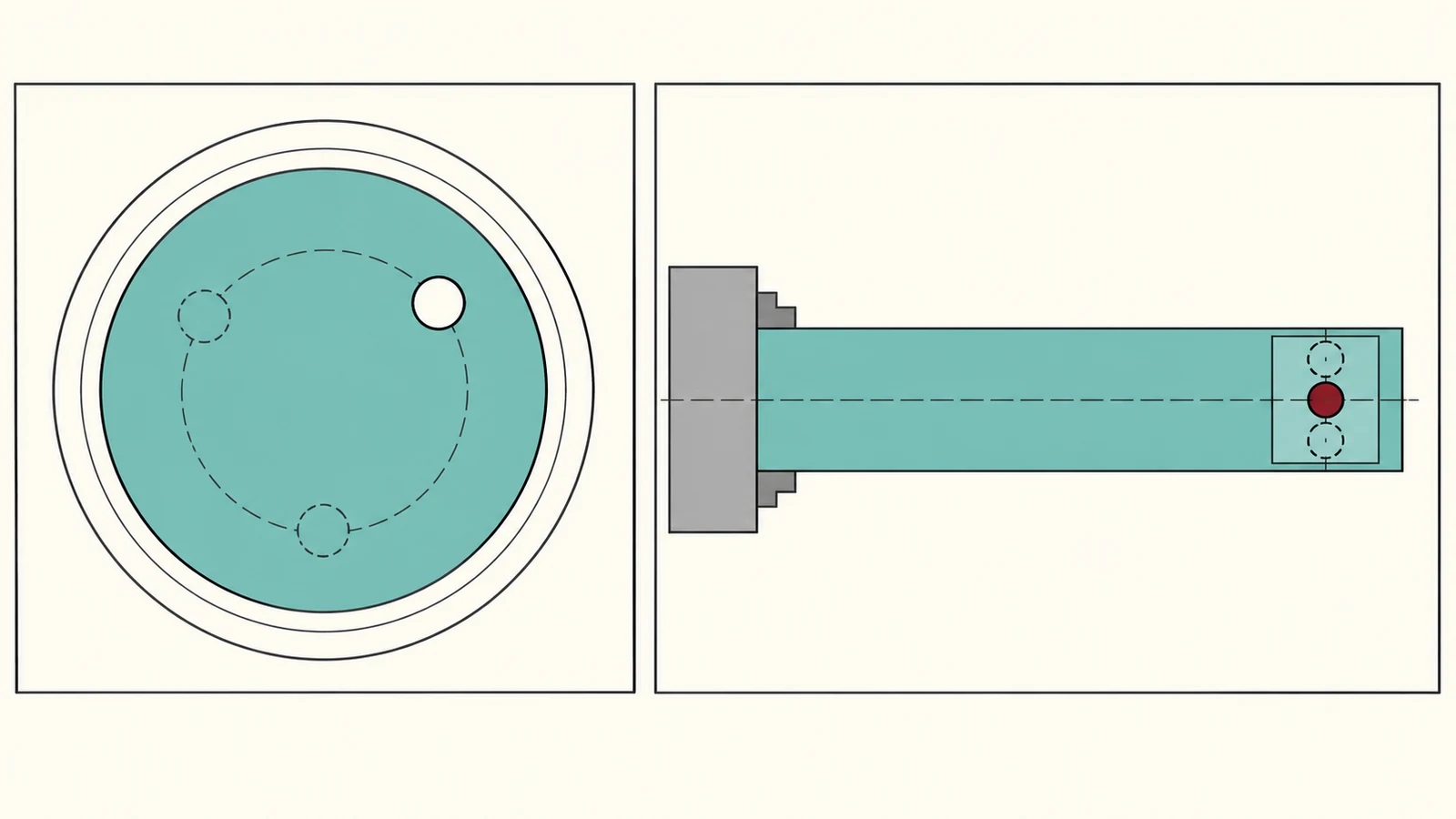
Review the full setup and datum chain
Before fixing the route, check the turned axis, the angular datum, and the location of the secondary feature in one coordinate framework. If the feature is clocked from a flat or a cross-hole, specify how that reference relates to the turning centerline. Otherwise, the programmer and inspector may create different zero references even when the toolpath is internally consistent.
Review the part’s sequence from stock to finished geometry. A face or diameter may be turned first and then used to establish the side-feature setup. If the part is re-clamped, consider how the angular and axial datums are recovered. A route with fewer setups can reduce handling, but only when the workholding and datum transfer are reliable.
Check tool clearance at the closest point, not just the nominal cutting position. The holder, chuck, tailstock, and adjacent workholding elements can constrain approach and retract moves. Evaluate chips and inspection access too: a motion that can cut the feature may still leave chips trapped or make the finished surface difficult to measure.
For a quote or design review, provide the full model, drawing, material, quantity, critical feature relationships, and any required surface finish. This gives manufacturing a basis to assess whether C-axis indexing, Y-axis travel, another setup, or a different process is justified. Avoid selecting an axis by name before the geometry and functional datums are clear.
Frequently asked questions
Does every live-tooling lathe have Y-axis motion?
No. Machine configurations vary. Confirm the actual available motion and tool arrangement rather than assuming that every lathe with live tooling includes the same axes.
Can C-axis positioning machine an off-center pocket?
It depends on the feature, tool orientation, and machine configuration. C-axis indexing controls angular position around the spindle; additional motion may be needed to reach or orient an off-center geometry.
Is a Y-axis lathe always the better choice for side features?
No. A simple radial feature may be handled with a fixed indexed approach. The useful question is whether the feature’s location and orientation require the additional travel and whether it improves the complete setup.