
Copper can be dimensionally stable and electrically useful, yet a machined edge may still look torn, smeared, or feathered. When that happens, “copper is soft” is not a useful diagnosis by itself. Burr formation depends on the exact copper grade, temper, edge geometry, tool condition, chip evacuation, and the way the final feature is inspected. A clean result starts by identifying where the edge is deforming and whether the drawing defines what “clean” means.
This guide focuses on burrs and edge tearing in machined copper—not on general copper grade selection or a broad process overview. It gives engineers and buyers a practical way to separate a cutting problem from an unclear acceptance requirement, then choose a corrective trial without changing several variables at once.
Identify the edge condition first
“Burr” describes several different outcomes. A thin foil-like lip at an exit edge, a rolled mushroom-shaped edge, a raised ridge at a slot intersection, and a ragged surface on a thin wall do not point to the same cause. Photograph the part under consistent light and mark the feature, cutting direction, and operation where the condition appears. If the part is deburred before inspection, preserve an as-machined sample; otherwise the evidence needed to diagnose the cutting edge is gone.
Also distinguish material pushed beyond the nominal boundary from a torn surface left inside the boundary. A projecting lip may be removed with a controlled edge break. A torn or smeared face can affect contact, conductivity, sealing, or appearance even after the lip is removed. If the part contains small cross-holes or intersecting passages, inspect both the entry and exit edges: a tool that cleans one side can push material into the opposite opening.
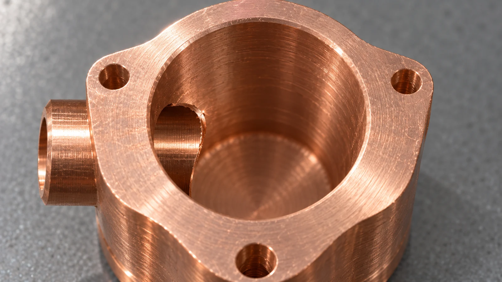
Finally, check whether the condition repeats in the same location. A burr that follows the tool exit on every part suggests a stable process mechanism. A defect that moves between parts may instead indicate changing edge sharpness, chip packing, workholding, or inconsistent manual finishing.
Why copper tears instead of shearing cleanly
Many copper grades are ductile. If the cutting edge is blunt, the edge can press and drag material before it separates. That creates a built-up edge or a smeared surface, and the final break may leave a lip rather than a crisp edge. A sharp, suitable tool and a stable cut matter, but the remedy is not simply to increase speed: chip load, tool geometry, lubrication strategy, and rigidity interact, and the right trial depends on the grade and feature.

Thin sections are especially vulnerable because the material can deflect as the tool exits. A long overhang, weak support, or a cut that leaves a narrow web until the final pass can turn a nominally clean shearing action into bending and tearing. Cross-holes and slots create interrupted cuts; the tool repeatedly enters and exits, while chips may be trapped at the intersection. For a part that also requires CNC milling, the tool path and part orientation should be reviewed together rather than treating every burr as a hand-finishing issue.
Material condition matters too. “Copper” can refer to different grades and tempers with different machinability and deformation behavior. A process proven on one stock condition should not automatically be copied to another. Verify the material designation and supplied condition before using a cutting adjustment to compensate for what may actually be a material substitution.
Trace the burr to the operation that made it
Start with a feature map. For each burr, record whether it forms at tool entry, tool exit, a slot end, a drilled breakthrough, or an intersecting feature. Then compare the part before and after each operation. This separates the operation that creates the burr from a later operation that merely folds or hides it.
| Observed condition | Likely mechanism to investigate | Useful first check |
|---|---|---|
| Thin lip at a consistent exit edge | Material is being pushed through before separation | Tool sharpness, exit support, and cut direction |
| Ragged edge around a cross-hole | Interrupted breakthrough or trapped chips | Sequence of intersecting operations and chip access |
| Smear on a broad machined face | Rubbing, built-up edge, or unstable chip formation | Tool condition and whether the cut is rubbing at the programmed engagement |
| Variable burr height across a batch | Changing tool edge, stock condition, or fixture support | Tool-life point, material lot, and clamping repeatability |
Use magnification appropriate to the acceptance requirement, not just a fingertip. Touch can detect a large lip but cannot reliably distinguish a small rolled edge from a torn surface or confirm that a functional edge is intact. If the part has an electrical contact face or a sealing land, inspect that functional region separately from a noncritical handling edge.
Review the cutting sequence before adding a secondary deburr step. A drilled hole followed by a cross-hole may leave a different intersection than the reverse sequence. If a finishing pass removes the visible burr but leaves loose fragments in a passage, the part may still fail assembly or cleanliness expectations. Record the sequence, tool, and condition of the part at each checkpoint.
Plan a controlled corrective trial
Choose one variable that matches the evidence. If the edge is consistently pushed at breakthrough, test a revised exit strategy or support condition. If the surface is smeared across a face, inspect the cutting edge and chip formation before changing the whole program. If chips are packed in an intersection, evaluate operation order and evacuation access. Keep the stock grade, fixture, inspection method, and remaining parameters stable so the trial can be interpreted.
For a fragile edge, a separate finishing pass can help only when it removes a defined amount of material without rounding a required corner or changing a fit. “Deburr all edges” is not sufficient for a sealing edge, bearing shoulder, narrow contact, or press-fit lead-in. These features may need a local dimension, a detail view, or an explicit no-break condition. If a uniform edge break is suitable for noncritical edges, state the permitted geometry and inspection boundary in the drawing note.
When a change improves appearance but causes a functional dimension to drift, it is not a successful correction. Compare the edge result with the part’s datum scheme, mating geometry, and post-machining finishing operations. Copper may also be plated or otherwise finished downstream; specify whether the edge is evaluated before or after that step, because the coating or finishing process can change the visible condition.
Make the edge requirement inspectable
Engineering, purchasing, and inspection need a shared acceptance criterion. Identify which edges are functional, which are safety or handling edges, and which are noncritical. For each critical edge, define the allowed burr or edge-break condition in a way that can be measured or clearly judged. Avoid relying on “sharp edges removed” where the amount of removal affects a mating face or passage.
For procurement, provide the material grade and temper, a drawing with critical edges identified, and any requirement that applies after plating or cleaning. The copper material information can help frame grade-specific discussion, but the drawing and agreed inspection method remain the authority for accepting a particular part. If the supplied stock differs from the specified condition, resolve that before changing the process recipe.
A good corrective record captures the defect location, likely mechanism, chosen parameter, sample size, inspection method, and whether the change affects any dimension or downstream operation. That record makes a later tool-life or material-lot investigation much faster than relying on a vague note that the part “looked rough.”
Frequently asked questions
Does a larger burr always mean the copper grade is wrong?
No. Tool wear, edge support, chip evacuation, and operation sequence can all change burr formation. Confirm the material designation and condition, then inspect the cutting process before concluding that the stock is responsible.
Can manual deburring solve copper edge tearing?
It can remove a permitted lip, but it does not explain or necessarily repair a smeared surface, a damaged contact edge, or loose chips inside a passage. Define the acceptable edge condition and verify the functional feature after finishing.
Should every copper edge receive the same edge break?
No. A uniform note is appropriate only for edges that share the same function and risk. Sealing faces, locating shoulders, small ports, and contact edges may need their own requirement or protection from material removal.
What should be checked first when burrs vary from part to part?
Compare tool condition and tool-life position, stock lot and temper, workholding support, and the exact operation sequence. Also verify that inspection uses the same lighting, magnification, and acceptance definition across the batch.