
Motor end bell bearing seat alignment is a relationship problem, not a bore-size problem. A bearing seat can meet its diameter requirement while the bearing axis, housing pilot, mounting face, and bolt pattern still disagree about where the rotor belongs. The drawing should make the assembled locating chain explicit, then the machining and inspection plans should preserve that same chain.
For a motor end bell, start from the bearing and frame interfaces that actually locate the part. Identify which surface seats against the motor frame, which register centers the end bell, which bore supports the bearing, and which shoulder controls axial seating. The functional arrangement—not a generic “concentricity” note—should determine the datum scheme.
On this page: Locate the assembled chain · Choose useful datums · Separate fit from alignment · Plan the machining sequence · Inspect the relationship
Start with the assembled locating chain
Draw the stack in the order it is assembled: frame or housing, end bell register, bearing outer ring, bearing inner ring, and shaft. The end bell may locate through a pilot diameter, a mounting face, fasteners, or a combination of these features. The bearing seat then locates one end of the rotating assembly. The required controls depend on that actual arrangement and on the mating component drawing.
This is why motor end bell bearing seat alignment should be reviewed with the mating frame and bearing details rather than specified in isolation. If the pilot controls centering, the bearing bore must be related to that pilot. If a face establishes axial seating, its relationship to the bore axis and bearing shoulder matters. The bolt circle should be located from the same functional reference where the design requires it, rather than treated as an unrelated pattern.
Choose datums that represent the motor interface
A useful datum reference frame reproduces how the part is located in assembly and inspection. Depending on the design, a mounting face may establish the primary plane while a cylindrical register establishes the axis and a separate feature clocks rotation. Other end bells may use a bore or pilot axis as the primary reference. There is no universal A-B-C sequence for every motor geometry.
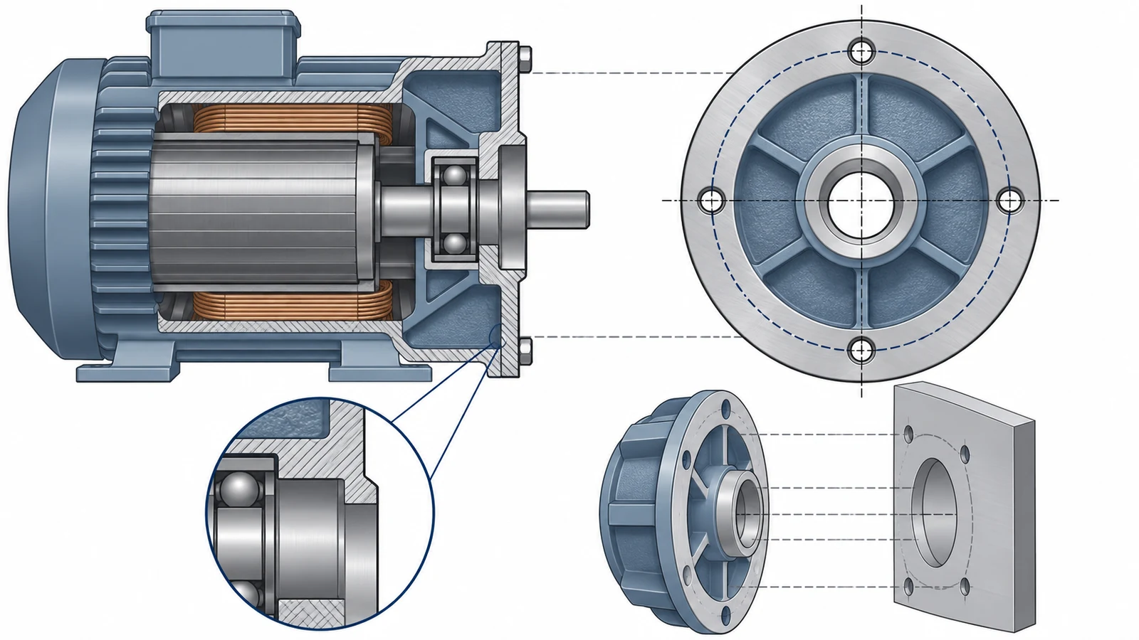
Make each datum feature physically identifiable and accessible. A datum placed on a broad but nonfunctional cast surface may be easy to touch yet fail to represent the assembled condition. Conversely, selecting the bearing bore as the sole reference can hide a position error between that bore and the frame pilot. State the datum precedence and the controlled relationships on the released drawing.
Keep bearing fit separate from axis alignment
Seat diameter and fit describe the relationship between the bearing outer ring and its bore. Roundness, cylindricity, shoulder squareness, and the bore-to-pilot relationship describe other parts of the geometry. One does not automatically guarantee the others. The bearing and motor designer should define the fit and acceptance limits for the specific bearing, load, temperature, and assembly method.
For that reason, motor end bell bearing seat alignment should not be reduced to a nominal diameter or a generic tight tolerance. Specify only controls that serve a functional requirement, and state the datum references used to evaluate them. A drawing review can also distinguish the bearing seat’s size tolerance from the geometric tolerance that controls its axis relative to the frame register.
Plan machining around the datum transfer
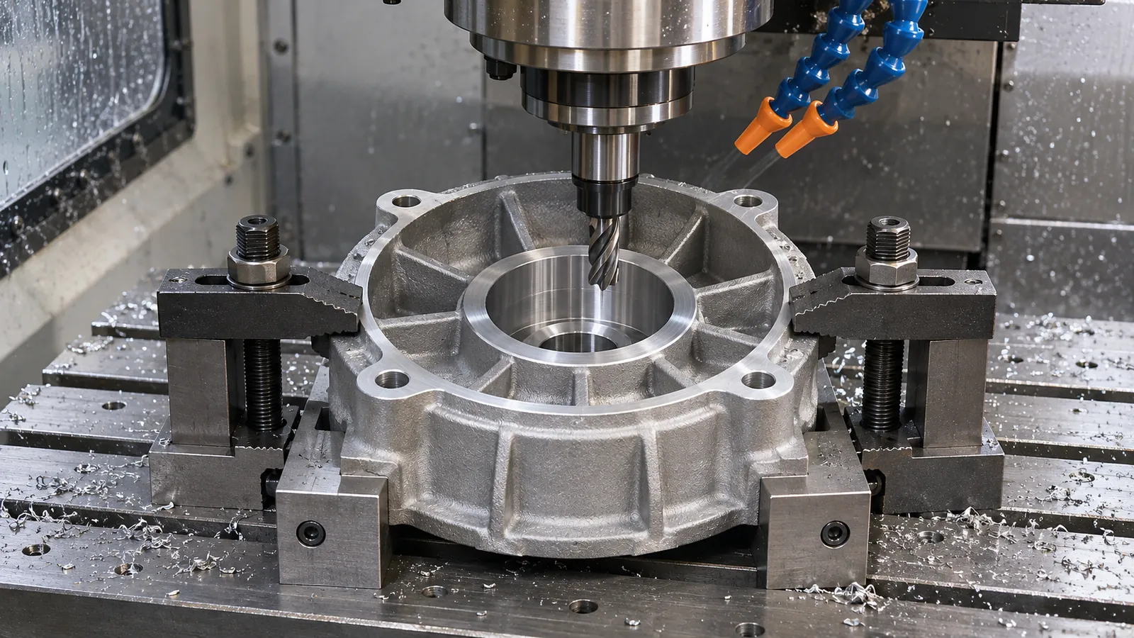
When machine access and part geometry permit, finishing the bearing bore and its locating pilot without losing the functional reference can reduce setup-to-setup variation. That is a process option, not a blanket capability promise: thin flanges, ribs, tool access, stock condition, and clamping can change the best sequence. Roughing, support, and finish cuts should be arranged so that later operations do not distort a previously finished locating surface.
If a second setup is necessary, define how the first finished feature is re-established. A fixture that references a different face from the drawing’s assembly datum can create a consistent but incorrect relationship. The process plan should identify the locating features, clamping points, and operation where the critical bore-to-pilot relationship is established. Related enclosure machining context is available on the site’s CNC milled enclosures page.
Inspect the relationship the drawing controls
Inspection should reproduce the specified datum reference frame and report the relationship that matters: bore size and form, pilot size, axis alignment, shoulder orientation, and hole-pattern position as applicable. A CMM may be suitable for a defined geometric relationship; a qualified functional fixture may be useful for an assembly interface. The method must match the drawing and the feature’s access, not an assumed universal check.
Where clamping could affect a thin end bell, compare the part in the supported measurement condition with the released condition when the drawing or inspection plan requires it. Record the setup and datum simulation so the supplier, motor assembler, and inspector are checking the same geometry.
What to include in a drawing review
- Identify the frame pilot, mounting face, bearing bore, shoulder, and bolt pattern that control assembly.
- Show datum precedence and geometric relationships from the functional interfaces.
- State bearing fit requirements separately from form and alignment controls.
- Agree how the datum scheme will be reproduced in machining and acceptance inspection.
- Resolve coating, deburring, and post-finish measurement conditions on the drawing or purchase specification.
In short, motor end bell bearing seat alignment is reliable when the drawing, setup, and inspection all preserve one assembly-relevant reference chain. Confirm that chain with the mating frame and bearing specifications before tightening tolerances; the purpose is repeatable location, not a tolerance number chosen without context.