
RF housing lid contact surface finish affects whether a conductive joint behaves as intended, but a finish callout alone cannot guarantee RF shielding or electrical continuity. The lid, enclosure land, fastener pattern, gasket if present, coating system, and inspection condition work together. Define the joint as an interface with a purpose, then make the drawing state which surfaces must remain in contact and how that condition will be verified.
This article focuses on the metal-to-metal lid perimeter and its machined contact land. It does not specify an enclosure’s RF performance, gasket material, or coating process; those depend on the operating frequency, design, environment, and qualification plan.
Begin with the joint’s electrical and mechanical role
First identify whether the lid joint is intended to provide electrical bonding, compress a conductive gasket, close a cavity, or perform more than one of these functions. Those cases do not automatically use the same geometry. A gasketed joint needs a defined compression region and a stable support surface; direct metal contact depends on the condition of the mating lands and the clamping arrangement.
Map the contact path around the perimeter. Mark the land width, corners, fastener locations, connector interfaces, and any interruptions caused by steps or openings. On a complex RF enclosure, the contact path may need to cross several machined faces. The drawing should make clear which of those surfaces are functionally connected and which are merely cosmetic.
Specify the land before choosing a finish note
Flatness, waviness, local damage, burrs, and surface texture can all affect how a lid meets its housing. A broad average roughness value does not describe every local gap or guarantee intimate contact. Likewise, a very smooth surface is not a substitute for a clear datum scheme, controlled clamping, or a compatible finish system.
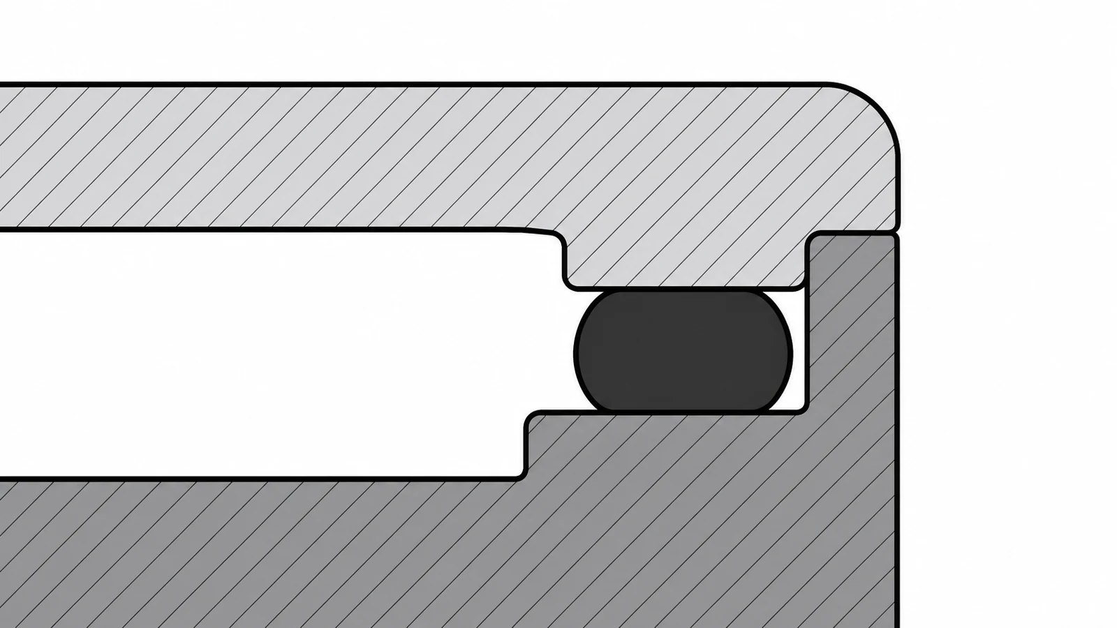
Specify the RF housing lid contact surface finish only after the design has identified the functional land and its mating condition. Use a surface texture requirement where it serves the joint, and add geometric controls when a measurable form or orientation requirement is necessary. Avoid applying a tight finish callout to every exterior face when only a defined perimeter is functional.
If the design uses a conductive gasket, coordinate land width and flatness with the gasket supplier’s installation requirements and the specified compression range. For direct metal contact, decide how conversion coatings, anodizing, plating, paint, or masking affect the contact zone. Coating thickness and electrical behavior vary by process; do not assume that a generic finish preserves the intended bond.
Coordinate machining, coating, and assembly
Machining plans should protect the contact land from tool marks, raised burrs, clamp damage, and later handling. Establish the land from datums that relate to the lid locating features and cavity geometry. If the part changes setups, define how the first reference is transferred so the contact perimeter does not shift relative to the lid or fasteners.
Make the manufacturing sequence explicit where finish operations affect the interface: machine, deburr, clean, mask or coat as specified, then inspect the required post-finish condition. The sequence is design-specific. A drawing or purchase specification should identify whether dimensions and surface requirements apply before or after coating, and who is responsible for masking or finish verification.
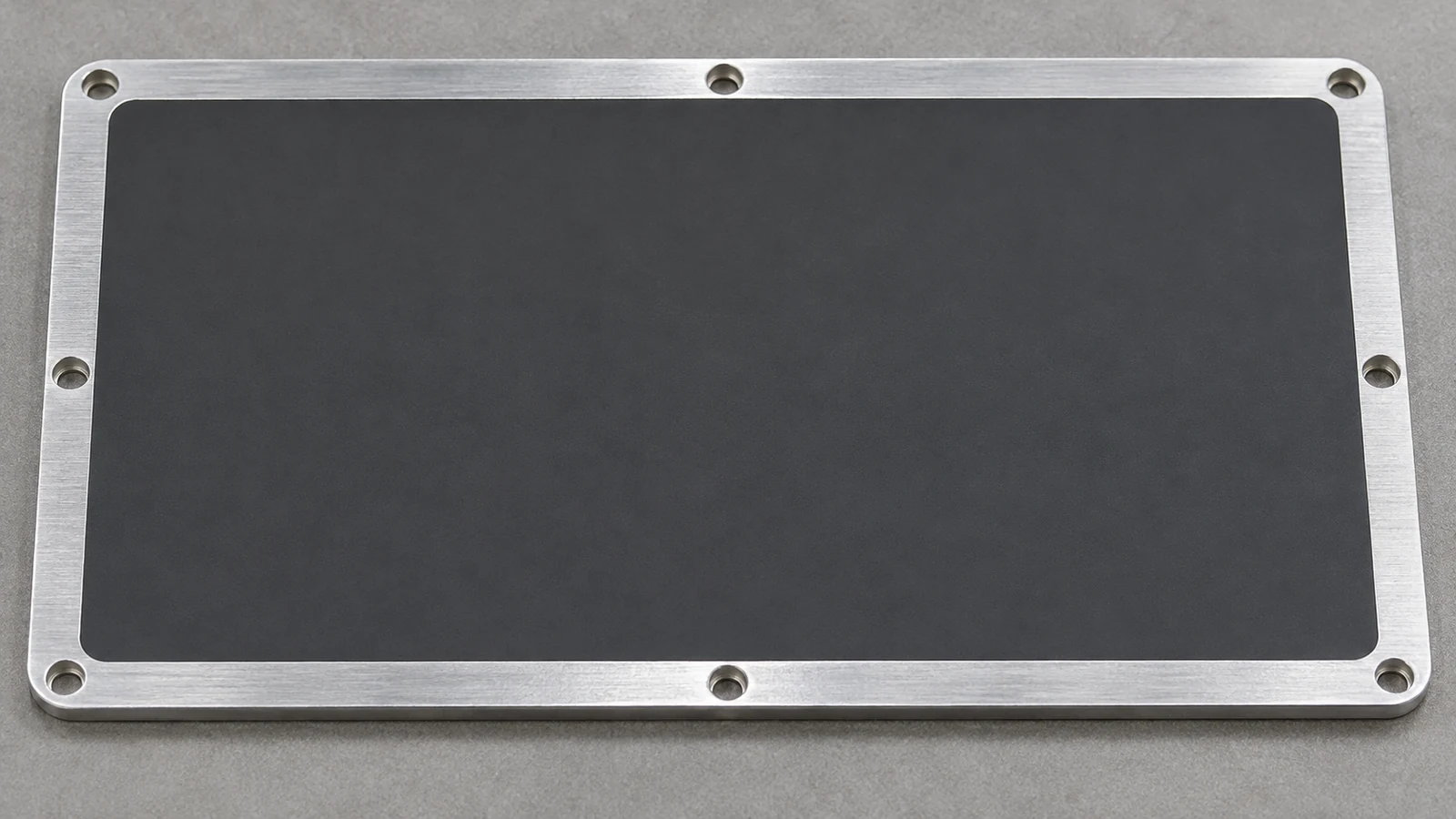
Enclosure geometry and access also matter. Deep cavities, thin walls, and interrupted perimeter lands can complicate clamping and measurement. The site’s CNC milled enclosures page describes the related machined-housing scope; project-specific RF performance remains a separate design and qualification responsibility.
Verify the interface in its stated condition
An inspection plan should connect each requirement to an observable feature. Check the land’s dimensions and form from the stated datum reference, inspect for burrs or damage, and confirm coating or masking boundaries where applicable. If assembly contact is critical, define an agreed method for evaluating the assembled joint instead of relying on a visual impression alone.
Record whether measurement occurs before or after the specified finish. A part can satisfy a pre-coating dimension and still fail the final interface if buildup changes a locating step or reduces clearance. The RF housing lid contact surface finish should therefore be reviewed alongside coating notes, gasket details, fastener locations, and acceptance criteria.
Drawing review questions
- Which perimeter or lands carry the intended electrical or gasket contact?
- What lid features locate the enclosure, and which datums control the contact path?
- Does the finish requirement apply before or after coating, and who controls masking?
- Are burr removal, cleaning, and handling requirements clear for the contact zone?
- How will the supplier and receiving inspection verify the specified condition?
A useful specification narrows the requirement to the surfaces that perform the joint’s function and states the relevant condition after manufacturing. That gives design, machining, finishing, assembly, and inspection teams a shared acceptance target without implying that surface finish alone proves shielding performance.