
This guide starts at the heat source and follows energy and coolant through contact surfaces, channels, seals, ports, joining, finishing, and testing. It focuses on design and sourcing decisions rather than claiming one universal tolerance or leak limit.
Draw the Thermal Path First
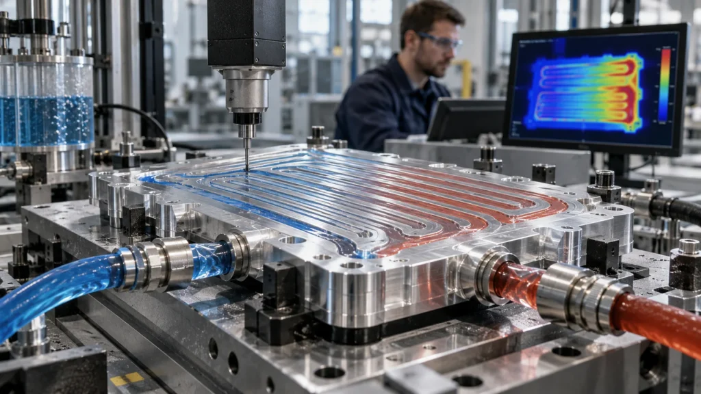 Map heat from the cell, power module, inverter, charger, motor controller, or electronics package through interface material, plate or housing, coolant wall, fluid, and heat rejection system. Identify contact area, allowable pressure, temperature range, flow distribution, pressure drop, and mechanical support.
This map distinguishes surfaces that control thermal contact from areas that are merely envelope. It also exposes conflicts: a thin wall may improve conduction but reduce stiffness; high clamp load may improve contact but distort a channel roof; aggressive lightweighting may weaken sealing support.
Map heat from the cell, power module, inverter, charger, motor controller, or electronics package through interface material, plate or housing, coolant wall, fluid, and heat rejection system. Identify contact area, allowable pressure, temperature range, flow distribution, pressure drop, and mechanical support.
This map distinguishes surfaces that control thermal contact from areas that are merely envelope. It also exposes conflicts: a thin wall may improve conduction but reduce stiffness; high clamp load may improve contact but distort a channel roof; aggressive lightweighting may weaken sealing support.
Cold-Plate Architecture Changes the Machining Route
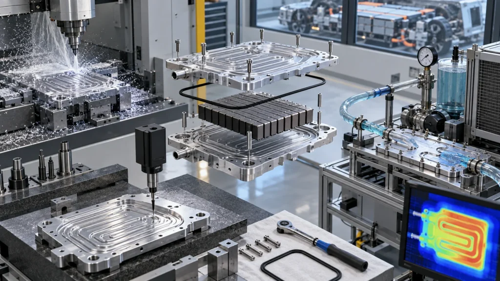 A machined channel plate with a joined cover, an extruded multi-channel plate with machined ports, a brazed assembly, or a cast housing with finish-machined interfaces each creates different risks. Select architecture by thermal duty, channel geometry, volume, joining capability, service pressure, corrosion, packaging, and inspection access.
Flatness Is an Assembly Condition, Not a Standalone Number
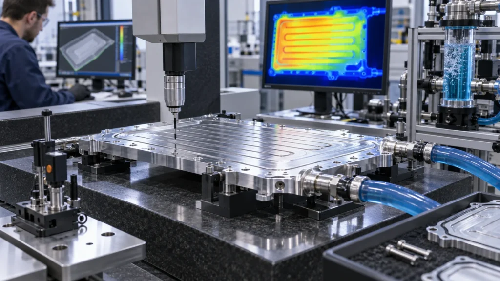 Contact performance depends on plate stiffness, free-state shape, mounting pattern, fastener preload, interface material thickness, mating-part geometry, temperature, and measurement method. An extremely tight free-state flatness limit may not predict installed contact if the assembly pulls the plate into another shape.
Define datum and measurement condition, contact zone, surface texture, and whether the requirement applies before or after joining and finishing. Simulate or test clamp load and thermal cycling where distortion matters. Large thin plates may require balanced machining, controlled supports, and stress-relief strategy.
Use CNC tolerance planning to separate thermal contact faces from nonfunctional envelope features.
Contact performance depends on plate stiffness, free-state shape, mounting pattern, fastener preload, interface material thickness, mating-part geometry, temperature, and measurement method. An extremely tight free-state flatness limit may not predict installed contact if the assembly pulls the plate into another shape.
Define datum and measurement condition, contact zone, surface texture, and whether the requirement applies before or after joining and finishing. Simulate or test clamp load and thermal cycling where distortion matters. Large thin plates may require balanced machining, controlled supports, and stress-relief strategy.
Use CNC tolerance planning to separate thermal contact faces from nonfunctional envelope features.
Seals and Ports Create Concentrated Risk
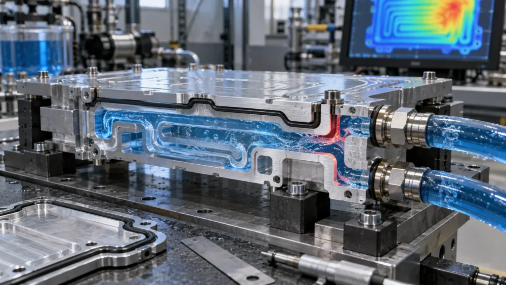 O-ring grooves, gasket lands, port threads, tube seats, and connector faces combine geometry, texture, edge condition, cleanliness, and assembly. Specify the seal system as a whole: material, groove design, compression intent, mating surface, pressure and temperature range, lubricant, and installation.
A groove can meet width and depth yet fail because of a scratch, burr, lead-in edge, distorted land, or coating buildup. Ports can leak through thread damage, poor seat geometry, misalignment, or debris. Identify protected zones and inspection methods before finishing.
O-ring grooves, gasket lands, port threads, tube seats, and connector faces combine geometry, texture, edge condition, cleanliness, and assembly. Specify the seal system as a whole: material, groove design, compression intent, mating surface, pressure and temperature range, lubricant, and installation.
A groove can meet width and depth yet fail because of a scratch, burr, lead-in edge, distorted land, or coating buildup. Ports can leak through thread damage, poor seat geometry, misalignment, or debris. Identify protected zones and inspection methods before finishing.
Internal Burrs and Cleanliness Affect Flow and Reliability
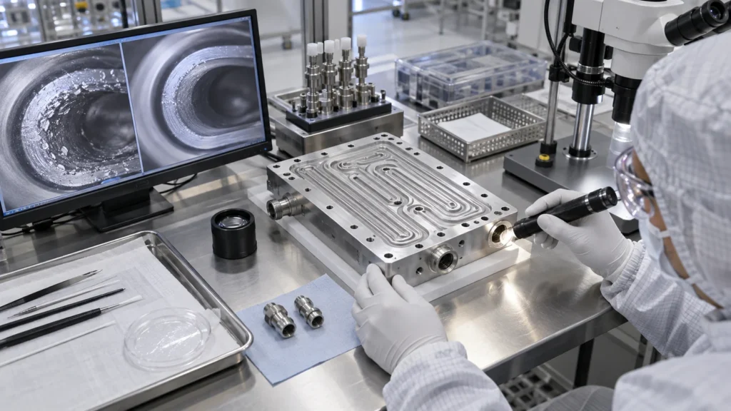 Intersecting drilled passages, milled channel edges, tapped ports, and joining debris can create loose particles or flow restrictions. Hidden burrs are difficult to verify after closure. Design access for deburring and flushing, choose cutting sequence to reduce burr formation, and inspect internal intersections before the cover is joined.
Cleaning requirements should define residue, fluid compatibility, drying, and package protection. A part that passes leak testing with debris inside can still damage pumps, valves, or narrow channels later. Preserve cleanliness through final assembly and shipping.
Intersecting drilled passages, milled channel edges, tapped ports, and joining debris can create loose particles or flow restrictions. Hidden burrs are difficult to verify after closure. Design access for deburring and flushing, choose cutting sequence to reduce burr formation, and inspect internal intersections before the cover is joined.
Cleaning requirements should define residue, fluid compatibility, drying, and package protection. A part that passes leak testing with debris inside can still damage pumps, valves, or narrow channels later. Preserve cleanliness through final assembly and shipping.
Joining Can Rewrite the Dimensions
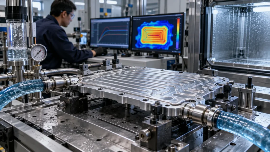 Brazing, welding, friction-stir welding, adhesive bonding, bolting, or gasketed closure each changes the route. Heat and restraint can distort contact faces, ports, and mounting patterns. Mechanical fastening adds preload and potential leak paths. Adhesive adds bond-line and cure control.
Decide which features are finished before joining and which need post-join machining. Provide datum features that survive the operation. Inspect at meaningful states rather than applying final requirements to a pre-join component without purpose.
Finishes may occur before or after joining and may need masking. Review corrosion couples, conductivity, seal surfaces, and thickness through the surface-finishing plan.
Brazing, welding, friction-stir welding, adhesive bonding, bolting, or gasketed closure each changes the route. Heat and restraint can distort contact faces, ports, and mounting patterns. Mechanical fastening adds preload and potential leak paths. Adhesive adds bond-line and cure control.
Decide which features are finished before joining and which need post-join machining. Provide datum features that survive the operation. Inspect at meaningful states rather than applying final requirements to a pre-join component without purpose.
Finishes may occur before or after joining and may need masking. Review corrosion couples, conductivity, seal surfaces, and thickness through the surface-finishing plan.
Verification Needs More Than a Leak Test
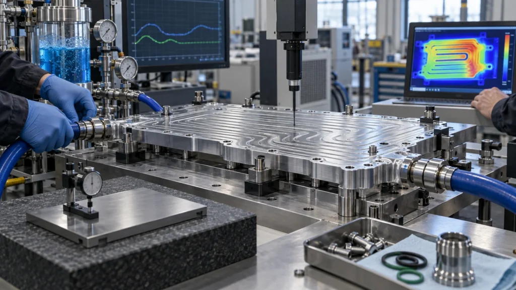 Leak testing confirms boundary integrity under the defined method; it does not confirm flow distribution, pressure drop, cleanliness, thermal resistance, flatness, or long-term durability. Build a verification matrix linking each function to its evidence.
Project requirements determine the actual methods and limits; do not copy values from unrelated cold plates.
Thermal-Component RFQ Checklist
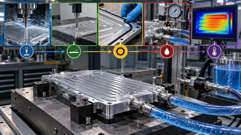 Provide CAD and controlled drawing, application and thermal boundary conditions, material and coolant compatibility, architecture or allowed alternatives, contact and seal zones, joining method, pressure and temperature conditions, flow targets, finish and masking, cleanliness, inspection, leak-test definition, quantity path, and validation records.
Ask the supplier to identify the process state for every critical result. This application-specific detail extends the parent CNC machining applications overview into EV thermal hardware.
Provide CAD and controlled drawing, application and thermal boundary conditions, material and coolant compatibility, architecture or allowed alternatives, contact and seal zones, joining method, pressure and temperature conditions, flow targets, finish and masking, cleanliness, inspection, leak-test definition, quantity path, and validation records.
Ask the supplier to identify the process state for every critical result. This application-specific detail extends the parent CNC machining applications overview into EV thermal hardware.
Cold-Plate FAQs
No. Depth affects wall stiffness, tool reach, chip evacuation, pressure loss, heat path, and joining. Channel design must balance thermal and mechanical performance.
Can a passed leak test guarantee field reliability?
No. Reliability also depends on test representativeness, seals, thermal and pressure cycling, vibration, corrosion, cleanliness, and assembly.
When should flatness be measured?
Measure at the process state defined by function—often after joining and finish, and sometimes under a specified support or restraint condition.