
This guide treats the joint as a mechanical system. It follows the motion axis from design through workholding, material removal, finishing, inspection, and assembly so engineers can specify what actually controls repeatable movement.
Map the Motion Chain Before Tolerancing
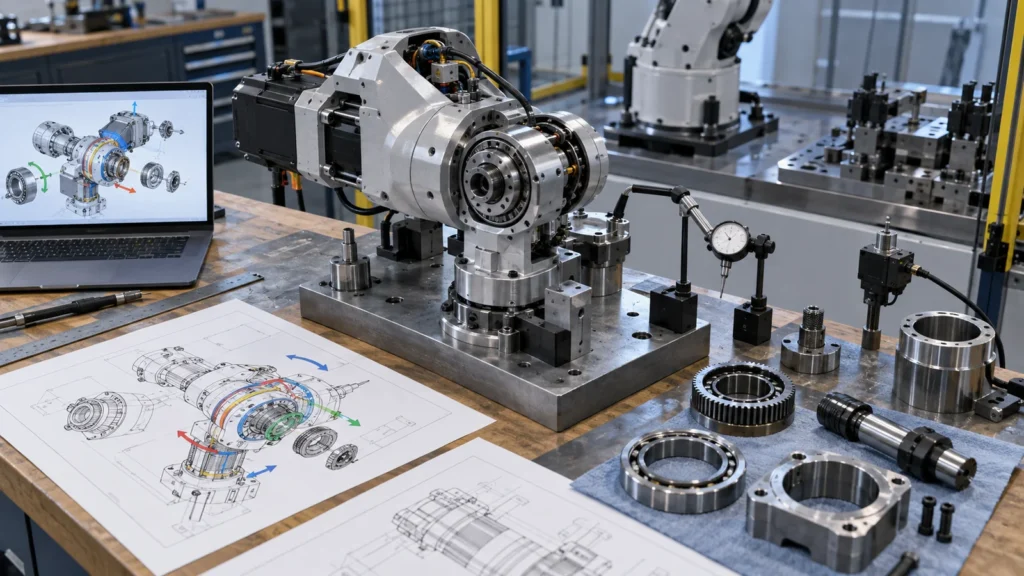 Draw the force and location chain from motor or actuator through gearbox, shaft, bearings, housing, link, and end load. Mark every pilot, shoulder, bore, face, dowel, fastener, and encoder feature that transfers position or load. This reveals which relationships influence radial runout, axial endplay, backlash, stiffness, and sensor alignment.
Do not tighten every dimension. A cosmetic cover and a bearing-seat relationship do not deserve the same control. Allocate tolerance to the chain based on allowable joint error, then preserve adjustment where assembly needs it.
Draw the force and location chain from motor or actuator through gearbox, shaft, bearings, housing, link, and end load. Mark every pilot, shoulder, bore, face, dowel, fastener, and encoder feature that transfers position or load. This reveals which relationships influence radial runout, axial endplay, backlash, stiffness, and sensor alignment.
Do not tighten every dimension. A cosmetic cover and a bearing-seat relationship do not deserve the same control. Allocate tolerance to the chain based on allowable joint error, then preserve adjustment where assembly needs it.
Build Datums Around the Functional Axis
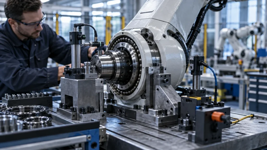 The primary datum system should represent how the joint locates in service. A mounting face may establish axial position, while a precision bore or pilot establishes the rotation axis and a secondary feature controls clocking. Selecting convenient stock faces as datums can make inspection easy but hide assembly error.
Process planning should keep related bores and faces in one setup where practical. When transfer is unavoidable, use machined reference features, probing, or fixtures that recover the functional axis. The robotic joint machining landing page can support commercial intent, while this article focuses on the engineering relationships behind it.
The primary datum system should represent how the joint locates in service. A mounting face may establish axial position, while a precision bore or pilot establishes the rotation axis and a secondary feature controls clocking. Selecting convenient stock faces as datums can make inspection easy but hide assembly error.
Process planning should keep related bores and faces in one setup where practical. When transfer is unavoidable, use machined reference features, probing, or fixtures that recover the functional axis. The robotic joint machining landing page can support commercial intent, while this article focuses on the engineering relationships behind it.
Fits and Preload Are System Decisions
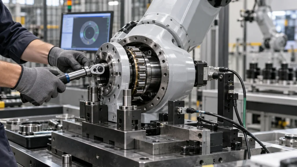 Bearing fits depend on load direction, ring rotation, material, wall thickness, temperature, assembly method, and service needs. A fit copied from another joint can create creep, excessive preload, difficult service, or housing distortion. Gearbox pilots and shaft interfaces need similar functional review.
Lightweight Housings Can Move Between Machine and Robot
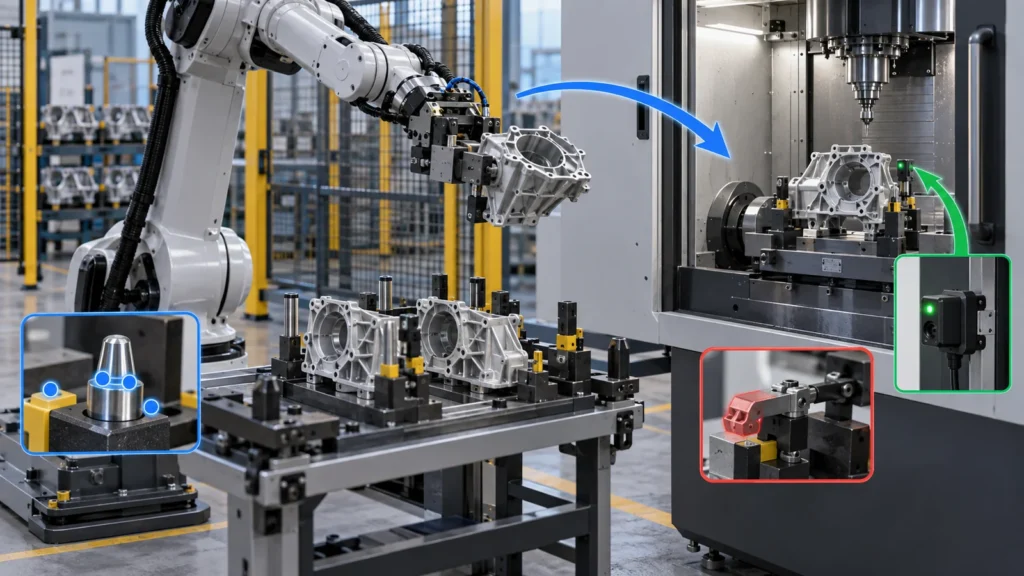 Pocketed aluminum joint bodies reduce mass but can release residual stress, deflect under clamps, or distort during finishing and assembly. Balanced roughing, stress-aware stock, staged machining, controlled clamping, and final cuts after relaxation can help. Measure critical geometry in the condition defined by the drawing.
Fastener preload can deform thin bearing walls even when free-state inspection passes. Model and test the assembled condition. Ribs and local bosses should support load paths without creating inaccessible pockets or unnecessary tool reach.
Pocketed aluminum joint bodies reduce mass but can release residual stress, deflect under clamps, or distort during finishing and assembly. Balanced roughing, stress-aware stock, staged machining, controlled clamping, and final cuts after relaxation can help. Measure critical geometry in the condition defined by the drawing.
Fastener preload can deform thin bearing walls even when free-state inspection passes. Model and test the assembled condition. Ribs and local bosses should support load paths without creating inaccessible pockets or unnecessary tool reach.
Assign Material and Finish by Interface
Aluminum offers low mass and machinability; steels can support compact loaded interfaces; stainless or titanium may suit corrosion, temperature, or weight priorities. Selection must consider stiffness, fatigue, wear, thread durability, galvanic contact, and supply—not only tensile strength.
Finishes can change fits and grounding. Anodizing may need masking at bearing seats and electrical contacts. Plating, passivation, hard coatings, and lubricants require interface-specific callouts. Review CNC surface finishes as part of the tolerance stack.
Inspect Relationships, Not Isolated Sizes
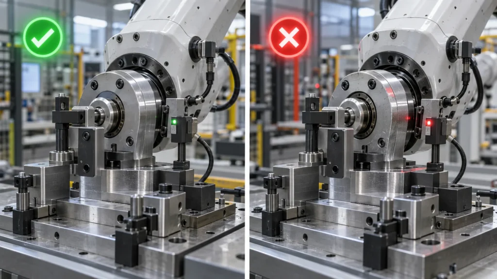 A caliper can confirm width but not whether two bearing bores share the intended axis. Inspection should cover coaxiality or position, face-to-axis orientation, runout, flatness, hole patterns, and surface requirements according to the drawing. Method and fixturing must represent the datum structure.
CMM inspection may suit complex relationships; bore gauges, roundness equipment, height gauges, or functional fixtures may provide better evidence for specific features. Define whether coating is present and whether the part is free or constrained.
A caliper can confirm width but not whether two bearing bores share the intended axis. Inspection should cover coaxiality or position, face-to-axis orientation, runout, flatness, hole patterns, and surface requirements according to the drawing. Method and fixturing must represent the datum structure.
CMM inspection may suit complex relationships; bore gauges, roundness equipment, height gauges, or functional fixtures may provide better evidence for specific features. Define whether coating is present and whether the part is free or constrained.
Close the Loop at Assembly
Record insertion force, bearing behavior, shim use, torque, joint drag, backlash, current draw, temperature, noise, and calibration results. When the assembly fails, do not immediately tighten the part drawing. Determine whether the cause is component geometry, purchased elements, cleanliness, lubrication, fastener sequence, or tolerance allocation.
Feed assembly evidence back to machining and inspection. A functional gauge or targeted relationship may be more valuable than adding tight limits to several unrelated dimensions. This reflects the parent CNC machining applications principle: process controls should follow application function.
Robotic-Joint RFQ Package
- Assembly context and motion-axis sketch
- 3D model plus datum-based drawing
- Bearing, gearbox, shaft, motor, and sensor interfaces
- Material, heat treatment, finish, masking, and lubrication
- Free-state and assembled-state requirements
- Critical relationship inspection and report needs
- Prototype quantity, production releases, and revision outlook
Joint Machining FAQs
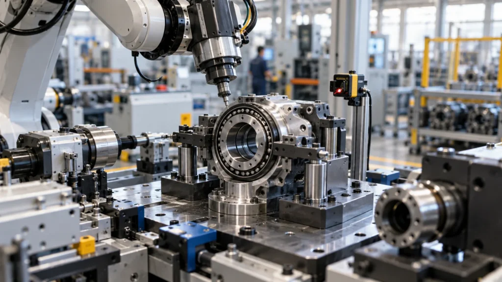
It is often beneficial for related axes, but geometry and equipment determine feasibility. A controlled transfer can also work when datums and verification preserve the relationship.
Does a tighter bearing fit remove backlash?
Not by itself. Backlash can originate in gears, splines, shafts, bearings, housing relationships, fasteners, or control compensation. Excessive fit can add heat and damage.
When is five-axis machining useful?
It can reduce setups for multi-face housings and preserve feature relationships, but axis count should follow access and datum needs rather than become a drawing requirement.