
AIチップ冷却における精密加工の重要な役割
人工知能の絶え間ない進歩はシリコンの基盤の上に築かれていますが、その真の可能性が解き放たれるのは、そのシリコンが最高性能で動作できる場合に限られます。機械学習、深層ニューラルネットワーク、複雑なデータ分析の頭脳であるAIチップは、膨大な量の電力を消費します。この電力は純粋な計算に変換されるのではなく、そのかなりの部分が廃熱となります。この熱エネルギーが極めて効率的に管理されなければ、性能の低下、寿命の短縮、そして壊滅的な故障を引き起こします。ここで、AI革命の縁の下の力持ちが登場します。それが精密加工されたヒートシンクです。 ai chip heatsink machining のプロセスは単なる製造工程ではなく、理論上の計算能力と実用的で信頼性の高い動作との間のギャップを埋める重要なエンジニアリング分野です。現代の加工によって実現されるミクロンレベルの精度と高度な熱設計がなければ、AIを支える高密度・高ワット数のプロセッサは、自らの熱負荷の下で単純に溶けてしまうでしょう。したがって、加工の役割は基盤的であり、原材料を、チップ上のトランジスタそのものと同じくらいシステム機能に不可欠な、洗練された熱伝導路へと変えるのです。.
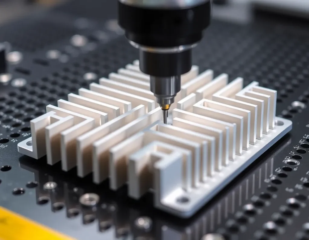
AIチップヒートシンク加工とは?プロセスとその構成要素の定義
AIチップヒートシンク加工は、AIプロセッサに物理的に取り付けて、その繊細なシリコンダイから熱を逃がす金属部品を作製することに焦点を当てた、精密製造の専門的な一分野です。その核心は、高熱伝導性金属のブロックやシートを、厳密な公差で複雑な形状に成形する除去加工プロセスです。最終製品は単なる金属片ではなく、いくつかの主要な構成要素からなる統合的な熱ソリューションです。多くの場合鏡面のように平坦なベースプレートは、チップと密接に接触します。スカイビング、フライス加工、または鍛造によって形成されるフィンは、冷却空気や液体に曝される表面積を劇的に増加させます。ヒートパイプやベーパーチャンバーは、集中したホットスポットからフィンアレイ全体へと熱を急速に拡散するために、しばしばアセンブリ内に埋め込まれます。加工プロセスは、熱界面の完全性、フィン構造の効率、そして冷却ソリューション全体の堅牢性を決定します。これは機械工学、材料科学、熱物理学の融合であり、AIハードウェアの独自かつ厳しい仕様を満たすためにコンピュータ制御の精度で実行されます。.
AIチップが高度なヒートシンクを必要とする理由:熱管理の不可欠性
現代のAIチップがもたらす熱的課題は、コンピューティングの歴史において前例のないものです。従来のCPUやGPUも相当な熱を発生させますが、GPU(グラフィックス処理ユニット)やTPU(テンソル処理ユニット)のようなAIアクセラレータは、電力密度を新たな極限まで押し上げます。これらのチップは、膨大な行列演算の並列処理のために設計されており、そのタスクは数十億のトランジスタを同時にアクティブに保ちます。このアーキテクチャ上の焦点により、単一パッケージで700ワットを超えることもある熱設計電力(TDP)定格が生じ、熱流束密度はその電力を時に切手よりも小さい領域に集中させます。従来の冷却ソリューションは全く不十分になります。AIチップ用の高度なヒートシンクは、いくつかの偉業を成し遂げなければなりません。すなわち、狭い領域からほぼ瞬時に強烈な熱を吸収し、局所的な過熱(「ホットスポッティング」として知られる現象)を防ぐためにその熱を横方向に拡散し、そして最大の効率で環境へ放出することです。この連鎖のいずれかの時点で失敗すると、チップは自己保護のために周波数をダウンクロックし、まさに最大化するように設計された指標である計算速度を直接犠牲にします。したがって、精密加工されたヒートシンクによる高度な熱管理は贅沢品ではなく、数十億ドル規模のAIトレーニングクラスタや推論サーバの完全性、性能、投資収益率を維持するための絶対的な不可欠事項です。.
AIヒートシンクの主要な加工プロセス:CNCフライス加工、スカイビング、鍛造
AIの熱管理の厳しい要求を満たすために、メーカーは高度な加工プロセスの一式を採用し、それぞれが特定の性能と形状要件に合わせて選択されます。.
CNCフライス加工
コンピュータ数値制御(CNC)フライス加工は、ヒートシンク製造の多用途な主力です。多軸機械を使用し、切削工具が固体金属ブロックをミクロン単位で測定される公差で複雑な形状に彫刻します。このプロセスは、独自のベースプレート形状、複雑な取り付け機能、液冷用の統合チャネルの作製に理想的です。AIヒートシンクでは、5軸CNCフライス加工により、標準的な加工では不可能なテーパーフィンやアンダーカットの作製が可能になり、気流と構造的完全性の両方を最適化します。CNCフライス加工の精度は、最適なチップ接触のための完全に平坦なベースを保証し、これは効果的な熱伝達のための譲れない要件です。.
スカイビング
スカイビング(またはスカーフィング)は、単一の金属ブロックから極めて薄い高アスペクト比のフィンを製造する特殊なプロセスです。鋭利で精密な刃がモノリシックなベースから薄い金属層を剥ぎ取り、持ち上げて連続したフィンを形成します。これにより、フィンがベースと一体となったワンピース構造が生まれ、別々に取り付けられたフィン間の接合部に見られる熱抵抗を排除します。スカイブ加工されたヒートシンクは、高い表面積と構造的堅牢性の優れたバランスを提供し、高性能空冷AIシステムに人気の選択肢となっています。スカイブ加工されたフィンの密度と薄さは、限られた容積内で放熱を最大化します。.
鍛造
鍛造は、高温または低温で金属に巨大な圧力を加えて成形するプロセスです。ヒートシンクにおいて、鍛造は優れた結晶粒構造を持つ強固で高密度なフィンアレイを作成するためによく使用されます。このプロセスは、結晶粒の流れをフィンの形状に沿わせることで、金属の機械的および熱的特性を向上させます。鍛造ヒートシンクはその耐久性と信頼性で知られ、機械的衝撃や振動が懸念される用途でよく使用されます。フィン密度はスカイビング加工部品には及ばないかもしれませんが、鍛造ヒートシンクはデータセンター用途で一般的な大量生産において卓越した構造性能と一貫した品質を提供します。.
多くの場合、これらのプロセスは組み合わされます。ヒートシンクは、CNC加工されたベースにヒートパイプを埋め込み、その上にスカイビングまたは鍛造のフィンスタックを載せたハイブリッドソリューションを採用し、各技術の強みを活かすことができます。.
高性能AIヒートシンクのための材料選択:銅、アルミニウム、および複合材料
材料の選択は、熱的および経済的な基本的な決定です。 ai chip heatsink machining. 主要な候補材料はそれぞれ、熱伝導率、重量、コスト、製造性の間で異なるトレードオフを提供します。.
銅
銅は熱伝導率のゴールドスタンダードであり、アルミニウムよりも約60%優れた熱伝達を提供します。このため、最も要求の厳しいAI冷却用途、特に集中したホットスポットから熱を迅速に吸収・拡散する必要があるベースプレートやベーパーチャンバーなどのコンポーネントに好まれる材料です。その優れた熱伝導率には欠点もあります。銅は著しく重く(アルミニウムの約3倍の密度)、原材料コストとその粘り強い性質による加工の難しさの両面でより高価です。しかし、最高の熱性能、特に液冷コールドプレートや直接ダイ冷却ソリューションでは、銅の利点はしばしば不可欠です。.
アルミニウム
アルミニウム合金は、量産ヒートシンク製造で最も一般的な材料であり、性能、重量、コストの優れたバランスを提供します。その熱伝導率は銅より低いものの、特に表面積を増やす優れた設計と組み合わせると、依然として非常に効果的です。アルミニウムははるかに軽く、高速で加工しやすく、耐食性にも優れています。重量とコストが重要な要素であり、強力なファンや液体ループで冷却を強化できる多くのAIサーバー用途では、アルミニウムヒートシンクは高度に最適化されたソリューションを提供します。.
複合材料と先進合金
純金属の限界を超えるために、業界は先進材料に目を向けています。これには、アルミニウム基複合材料(例:ダイヤモンドや炭化ケイ素粒子を注入したアルミニウム)が含まれ、銅に匹敵するかそれを超える熱伝導率を提供しながら、より低い密度を維持できます。ベーパーチャンバー材料も進化しており、より薄い壁とより効率的なウィック構造を備えています。さらに、熱界面材料(TIM)—チップとヒートシンクの間のペースト、パッド、または液体金属—は、システムにおける重要な「材料」です。グラフェン注入化合物や相変化材料などのTIMの進歩は、最も重要な接合部での熱障壁を最小化することで、ヒートシンクアセンブリ全体の有効性に直接影響を与えます。.
最適な熱性能のための設計とエンジニアリングの考慮事項
効果的なAIヒートシンクの作成は、機械的、熱的、および空力的設計が融合する多分野最適化の実践です。.
熱抵抗ネットワークは中心的な概念です。エンジニアは、シリコンダイから熱界面材料を通り、ヒートシンクベースに入り、フィンに沿って、最終的に冷却材(空気または液体)に至るまで、あらゆる点で抵抗を最小化する必要があります。ベースの厚さと面積は、ボトルネックにならずに熱を拡散するように計算されます。フィンの形状—高さ、厚さ、間隔、形状—は、計算流体力学(CFD)を使用して最適化され、特定のファン出力と騒音特性に対して熱伝達を最大化します。空冷設計では、気流に対するフィンの配置が重要です。平行フィンスタックが一般的ですが、千鳥配置やピンフィンアレイは、限られた空間で乱流と熱伝達を強化できます。.
For liquid-cooled systems, the design shifts to cold plates. Here, the internal microchannel structure is paramount. The pattern, width, and depth of these channels dictate flow resistance and heat exchange efficiency. Designs must balance high turbulence for good heat transfer with low pressure drop to minimize pump power. Jet impingement cooling, where fluid is directed in high-velocity streams directly at the back of the chip’s hotspot, represents another advanced design approach for the most extreme thermal loads.
Mounting pressure and flatness are critical mechanical considerations. Insufficient pressure leads to high thermal interface resistance, while excessive pressure can warp the chip substrate or heatsink. A machined flatness measured in microns across the base ensures full contact. Finally, the entire design is constrained by the physical envelope of the server chassis, requiring innovative 3D packaging to fit maximum cooling capacity into minimal space. This holistic engineering effort transforms a passive metal component into an active, system-level thermal management solution.
Surface Finishing and Coating Techniques to Enhance Heat Dissipation
The journey of an AI heatsink does not end with precision machining. The final surface condition of the metal plays a decisive role in its thermal performance. A mirror-smooth finish might seem ideal, but for maximizing heat dissipation, controlled roughness and specialized coatings are often the true heroes. These post-machining processes target the two primary thermal resistances: the interface between the chip and heatsink base, and the interface between the fins and the cooling medium.
Starting at the base, the mounting surface that contacts the AI chip must be exceptionally flat to minimize air gaps. Machining achieves this flatness, but the microscopic peaks and valleys left by the cutting tool can trap air, a poor thermal conductor. Lapping is a common finishing technique used to create an optically flat surface, often specified with a roughness average (Ra) in the range of 0.1 to 0.8 micrometers. This ultra-smooth surface ensures maximum contact area for the thermal interface material (TIM), such as grease or a phase-change pad, leading to lower thermal resistance.
Conversely, the fin surfaces and other areas exposed to air or liquid coolant benefit from increased surface area. Techniques like chemical etching or sandblasting are employed to create a micro-textured surface. This controlled roughness increases the effective surface area for heat exchange, promoting better convection. For air-cooled heatsinks, this can lead to a measurable drop in thermal resistance. Another advanced method is the creation of micro-pin fins or porous structures through specialized machining or additive techniques, which drastically amplify surface area in a compact volume.
Coatings represent a more transformative approach. Nickel plating is frequently applied to copper heatsinks. While nickel has lower thermal conductivity than copper, it provides a durable, corrosion-resistant barrier that prevents copper oxidation. Oxidized copper loses its thermal efficiency, so the thin nickel layer preserves long-term performance. For high-performance applications, more exotic coatings come into play. Graphene or carbon nanotube-based coatings, applied through chemical vapor deposition, can significantly enhance thermal conductivity at the surface interface. Anti-oxidation coatings for aluminum, such as thin anodized layers or specialized ceramic coatings, serve a similar protective function while maintaining good thermal properties.
In two-phase cooling systems, where liquid boils and condenses, surface wettability is critical. Coatings can be engineered to modify the surface energy, promoting the formation of smaller, more frequent bubbles (nucleate boiling) which is highly efficient for heat removal. The synergy between the macro-scale geometry from ai chip heatsink machining and these micro- and nano-scale surface modifications is what pushes thermal management to its physical limits.
Quality Control and Testing: Ensuring Precision and Reliability
In an application where a failure can lead to throttling of a multi-million-dollar AI cluster or catastrophic hardware loss, quality control is non-negotiable. The precision demanded by AI heatsinks necessitates a rigorous, multi-stage inspection protocol that verifies dimensional accuracy, material integrity, and thermal performance. This process transforms a manufactured part into a certified thermal solution.
Dimensional inspection begins with the raw material, verifying alloy composition and properties, and continues through every machining step. Coordinate Measuring Machines (CMM) are indispensable. These robotic probes map the entire geometry of a heatsink—base flatness, fin thickness and spacing, channel dimensions, and mounting hole locations—with micron-level accuracy. The data is compared directly to the original CAD model, ensuring the physical part is a perfect embodiment of the optimized design. For complex internal channels in liquid cold plates, non-destructive techniques like X-ray computed tomography (CT) scanning are used. This creates a 3D volumetric image, revealing any internal defects, blockages, or deviations in channel paths that would impair fluid flow.
Surface quality is scrutinized with profilometers to measure roughness (Ra, Rz) and with visual inspection under high magnification to detect tool marks, scratches, or porosity. The integrity of bonded or brazed joints, common in stacked-fin or liquid cold plate designs, is tested through pressure decay tests or helium leak detection to ensure they are hermetically sealed and can withstand years of thermal cycling and pressure stress.
The ultimate validation is thermal performance testing. While computational fluid dynamics (CFD) models predict performance, real-world testing is essential. Heatsinks are mounted to a thermal test die—a device that simulates the power map and heat flux of an actual AI chip—inside a wind tunnel or liquid test loop. An array of thermocouples and pressure sensors collects data on thermal resistance (often reported as Ψ or θ), flow rate, and pressure drop. This testing confirms that the heatsink meets its design specifications under simulated operational loads. Reliability testing, including thermal shock cycling and long-duration burn-in tests, ensures the assembly will not degrade or fail in the field. This comprehensive QC regime guarantees that every heatsink is not just a piece of metal, but a reliable, high-performance component ready for the data center.
The Future of AI Heatsink Machining: Innovations and Industry Trends
The relentless growth of AI computational density ensures that thermal management will remain a primary bottleneck, driving continuous innovation in heatsink technology and manufacturing. The future of ai chip heatsink machining lies in greater integration, smarter materials, and hybrid manufacturing techniques that blur the lines between traditional and additive processes.
One dominant trend is the move toward direct cooling of the silicon. As traditional packaging reaches its limits, the heatsink is moving closer to the heat source. This includes technologies like direct-to-chip liquid cooling, where microfluidic channels are machined or etched directly into a silicon or ceramic interposer that sits atop the chip. The next evolution is monolithic cooling, where microscopic fins and channels are fabricated directly onto the backside of the silicon die itself using semiconductor etching techniques, effectively making the chip its own ultra-efficient heatsink. This level of integration will require unprecedented collaboration between chip foundries and precision machining specialists.
Additive manufacturing (3D printing) is transitioning from prototyping to full-scale production for high-value thermal solutions. Metal additive processes like Laser Powder Bed Fusion (LPBF) can create previously impossible geometries—such as conformal cooling channels that perfectly follow a chip’s hotspot pattern, or ultra-high aspect-ratio fins with complex lattice structures for immense surface area. The future will likely see hybrid systems where a baseplate is precision-machined for flatness, and then intricate fin stacks are printed directly onto it, combining the best of both technologies.
Material science will deliver the next leap. The development of metal matrix composites (MMCs), like copper-diamond or aluminum-graphite, promises materials with thermal conductivity surpassing pure copper while being lighter. Advanced thermal interface materials, possibly based on liquid metals or aligned carbon nanotubes, will further reduce the resistance between chip and cooler. Furthermore, the rise of embedded two-phase cooling systems, where a refrigerant is sealed inside a heatsink with an internal wick structure (a heat pipe scaled up to “vapor chamber” size for entire servers), will become more prevalent, offering near-isothermal cooling with no external liquid loops.
Finally, the industry is moving towards smarter, adaptive thermal management. This involves integrating micro-sensors into heatsinks to monitor temperature and pressure in real-time, feeding data to the AI system’s control software to dynamically adjust fan speeds, pump rates, or even computational workload distribution to optimize for efficiency and prevent thermal runaway. The heatsink evolves from a passive dumb mass into an intelligent, responsive component of the AI hardware stack.
主要ポイントのまとめ
The thermal management of AI chips is a critical engineering challenge directly enabled by advanced manufacturing. AI heatsink machining is a specialized field that transforms high-conductivity metals into complex, performance-critical components. The extraordinary thermal density of AI processors demands heatsinks that go far beyond simple metal blocks, requiring intricate fin arrays, liquid cold plates with turbulent microchannels, and perfect mounting surfaces.
Key processes like high-speed CNC milling, skiving, and forging are employed to create the necessary geometries from materials like copper, aluminum, and advanced composites. The design of these components is a holistic exercise in thermal, fluid, and mechanical engineering, balancing heat transfer efficiency against pressure drop and physical constraints. Post-machining surface treatments—from lapping for flatness to texturing for increased area and specialized coatings for protection or enhanced boiling—are essential to maximize performance.
Rigorous quality control, using tools like CMMs, CT scanners, and thermal test dies, ensures each heatsink meets precise dimensional and performance specifications, guaranteeing reliability in demanding data center environments. Looking ahead, the field is being reshaped by trends like direct-to-chip and monolithic cooling, the adoption of additive manufacturing for complex geometries, the development of next-generation composite materials, and the integration of intelligence for adaptive thermal management. The evolution of AI chip heatsink machining will continue to be a fundamental enabler of the world’s most powerful computing systems.
よくある質問(FAQ)
Why can’t we just use a standard CPU cooler for an AI chip?
Standard CPU coolers are designed for thermal design power (TDP) ratings typically under 300 watts, with a relatively uniform heat flux. AI chips, especially GPUs and TPUs, can exceed 700-1000 watts with concentrated hotspots that generate heat fluxes over 100 watts per square centimeter. A standard cooler lacks the specialized base geometry, dense fin array, and often the liquid cooling capability required to manage this intense, localized heat without causing thermal throttling or damage.
Is copper always better than aluminum for AI heatsinks?
Copper has about 60% higher thermal conductivity than aluminum, making it superior for transferring heat from the source. However, copper is nearly three times denser and more expensive. The choice involves a trade-off: for the highest-performance applications where every degree matters, copper or copper alloys are preferred, especially for the base. Aluminum is often used for fins in air coolers or entire heatsinks where weight, cost, and adequate performance are balanced. Advanced designs frequently use a copper base for heat acquisition and aluminum fins for cost-effective heat dissipation.
What is the benefit of a machined heatsink over a cast one?
Machining, particularly CNC machining, offers far superior precision, finer feature resolution, and better material integrity. Cast heatsinks can have porosity (tiny air bubbles) that act as thermal insulators, and they struggle to achieve the thin, closely-spaced fins or complex internal channels needed for AI cooling. Machining from a solid billet guarantees a dense, pore-free structure with exacting tolerances on fin thickness, base flatness, and channel dimensions, all crucial for optimal thermal contact and fluid dynamics.
How does liquid cooling work in an AI server heatsink?
A liquid-cooled AI heatsink, or cold plate, has a hollow interior machined with a network of microchannels. A coolant (often deionized water or a specialized fluid) is pumped through these channels. As it flows, it absorbs heat from the metal base contacting the hot chip. The heated liquid is then transported to a radiator (heat exchanger) elsewhere in the server rack, where it releases the heat to the ambient air, cools down, and is recirculated. This method is vastly more efficient than air at moving heat away from the source.
What does “thermal resistance” mean for a heatsink, and why is it important?
Thermal resistance (measured in °C/W) quantifies how effectively a heatsink transfers heat. It represents the temperature rise per watt of power dissipated. A lower thermal resistance means the heatsink can keep the chip cooler for a given power level. For AI chips, a target thermal resistance is a key design specification. It encompasses all resistances: from the chip junction to its case, through the thermal interface material, through the heatsink base and fins, and finally to the coolant or air. Minimizing this total resistance is the core goal of heatsink design and machining.
Are 3D-printed heatsinks as good as machined ones?
3D-printed (additively manufactured) heatsinks excel in creating complex, optimized geometries like conformal channels or lattice structures that are impossible to machine. They are becoming viable for high-performance applications. However, traditionally machined heatsinks from solid billets currently offer better absolute thermal conductivity due to the lack of layer boundaries and potential porosity inherent in some printing processes. The choice depends on the need for geometric complexity versus ultimate thermal performance. Often, the future lies in hybrid approaches combining both techniques.