
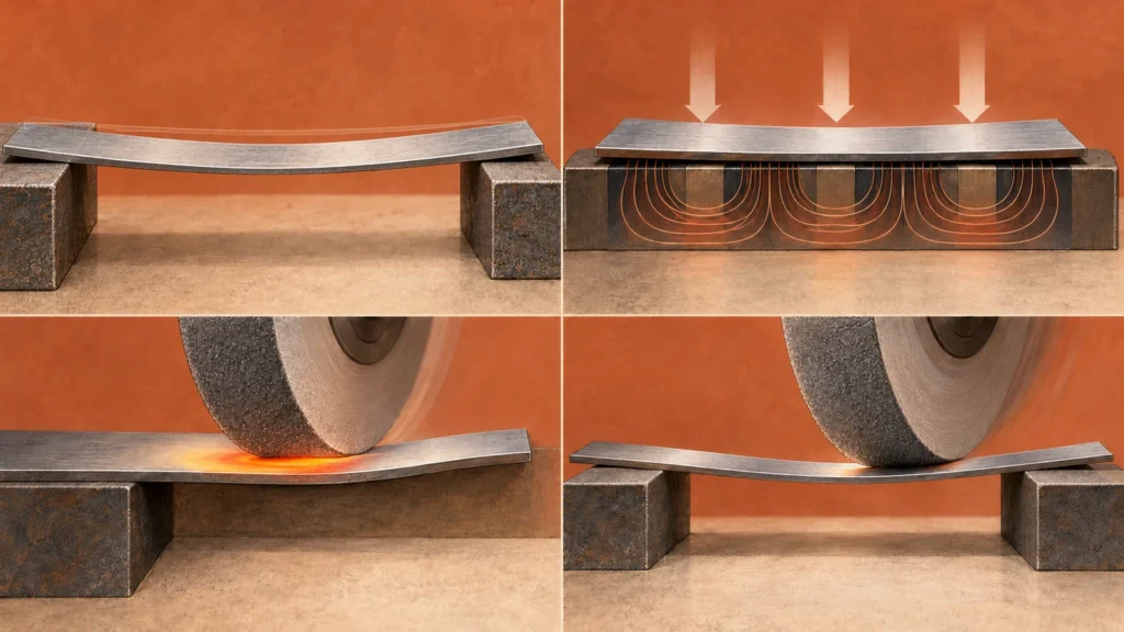
A thin part can leave a surface grinder flat under the chuck and spring into a bow after it is released. That does not automatically mean the final pass was wrong. Grinding may reveal residual stress, clamp or magnetic force may temporarily flatten the work, and heat can create a changing shape during the cycle. The useful question is when the distortion appears: before grinding, while held, immediately after release, or after the part cools.
Diagnosing that sequence is more effective than simply reducing the infeed or adding more spark-out. First map the free-state part, then separate workholding effects from material-stress and thermal effects. Only after the dominant mechanism is understood should the process or drawing be changed.
Locate when the shape changes
Begin with a consistent measurement plan. Mark the part orientation, support points, and measurement locations. Check flatness or profile before grinding, while the part is held if that is meaningful, immediately after release, and again after it reaches a stable temperature. A simple before-and-after map can reveal whether the part is being forced flat on the chuck or whether the shape changes as material is removed.
Use the same datum and support method for every reading. A thin plate can sag under its own weight or change shape when turned over. If measurement force is significant relative to section stiffness, a contact probe can deflect the part. A surface plate, indicator, CMM, or noncontact method may be appropriate depending on size and tolerance, but the measurement setup itself must not become an uncontrolled clamp.
Four mechanisms behind a bowed part
Residual-stress release: Rolled, extruded, cast, or previously machined stock can contain a nonuniform stress state. Removing material from one side changes the balance. The part may curve even when the grinding force and temperature are modest. Unequal stock removal on opposite faces makes the effect more likely to show up during a one-sided finish operation.
Workholding distortion: Magnetic chuck force, vacuum, clamps, burrs, chips, or a dirty support face can pull the part into a shape that is not its free state. Grinding that constrained shape produces a surface that appears flat while held but changes when the force is removed. Excessive clamping force can have a similar effect on a mechanically held thin section.
Thermal gradients: Grinding energy heats the contact zone. Uneven coolant delivery, a dull or loaded wheel, excessive contact, or interruptions can produce local temperature differences. As the work cools, temporary expansion disappears and the measured form may shift. Heat can also damage a surface, so a thermal issue should not be treated as a cosmetic variation.
Uneven support or process loading: A flexible section can deflect under wheel force, especially when the contact point is far from a support. Poorly distributed support can let one region lift or chatter. The wheel, machine, fixture, and part form one compliance system; changing only the programmed infeed may not fix a support problem.
- Record the incoming condition. Map the blank before roughing and note how it was cut, rolled, stress-relieved, or previously machined if that information is available.
- Check the contact surface. Remove burrs and confirm the support face and chuck are clean. Verify that the work sits consistently before the wheel touches it.
- Compare held and free-state readings. If the part changes mainly on release, suspect restraint or residual stress rather than a simple final-pass issue.
- Inspect the grinding pattern. Look for uneven contact, burn, chatter, or local discoloration. These observations are clues, not substitutes for measurement.
- Review the sequence. Compare how much stock is removed from each face and whether the part is roughed and finished in balanced stages.
- Change one process variable at a time. Adjust support, clamping, wheel condition, coolant, or removal sequence, then repeat the same measurements.
This sequence prevents a common mistake: holding a bowed plate flat with extra force, grinding it, and assuming the new surface proves the part is stable. The measurement after release is the one that matters if the component is used without that restraint.
Adjust the route without hiding the problem
When residual stress is likely, balanced stock removal can reduce sudden changes. Rough both faces in stages where geometry permits, leave a controlled finishing allowance, and allow the work to stabilize between operations when necessary. A stress-relief treatment may be considered only when material, specification, and downstream requirements allow it; heat treatment itself can change dimensions and must be planned rather than assumed.
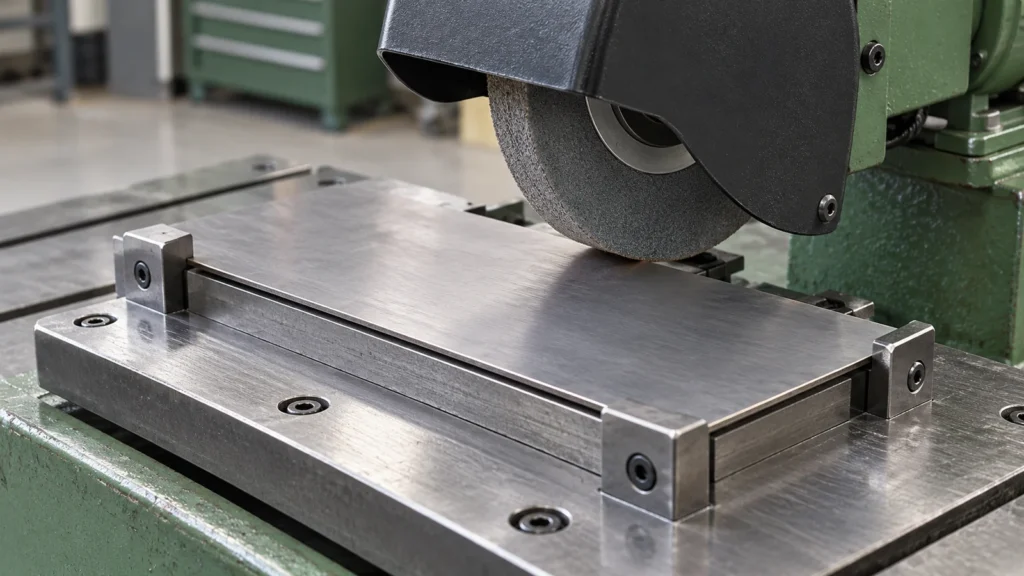
For workholding distortion, use the least force that keeps the part secure, improve support near the grind zone, and check whether a carrier, soft support, or alternative fixture is appropriate. The method must remain safe and repeatable. Do not improvise a fixture that can release the part into the wheel or compromise operator safety.
Define free-state acceptance
For a flexible component, the drawing or inspection plan should make the measurement condition explicit. State whether flatness is evaluated in a free state, on defined supports, or under a specified restraint. Identify the datum, measurement span, support points, and whether the part is measured before or after coating or assembly. Without those conditions, two inspectors can obtain different results from the same part.
Also distinguish flatness from thickness and parallelism. A plate may have uniform thickness but bow as a whole; it may be locally flat in zones but not parallel from face to face. Specify only the characteristics needed for function, then choose an inspection method that can evaluate them without forcing the part into shape.
If distortion remains after a controlled process, compare it with the functional assembly. A slightly bowed panel may be acceptable when installed against supports, while a warped locating plate may not be. Functional testing can supplement the drawing, but it should not replace a measurable requirement unless the acceptance agreement defines the test.
FAQ
Why does a ground plate look flat on the chuck but bend after release?
The chuck may be restraining the plate in a flatter shape than its free state. Grinding that constrained surface and then releasing the holding force exposes the underlying stress or elastic deformation.
Will lighter grinding eliminate thin-part distortion?
It may reduce heat or force-related deflection, but it will not remove residual stress or correct an unsuitable support condition. Diagnose the cause before changing the cycle.
Should thin parts always be stress-relieved?
No. Treatment suitability depends on material, prior processing, dimensional risk, specification, and the potential for the treatment itself to change shape. It should be an engineering decision.