
A freight train is not a single machining application. Its supporting equipment can include sensor mounts, instrument housings, spacers, bushings and other drawing-defined parts, each with a different job at the interface. For a non-safety-critical equipment component, the useful starting point is not the rail vehicle label: it is the mounting datum, mating geometry, environment and inspection state that determine whether the part fits its assembly.
This guide focuses on those machined interfaces. It does not establish suitability for brakes, couplers, axles, suspension or other safety-related systems; those require the responsible design authority, applicable qualification and supplier evidence. If the need is general process scope, see Capacità di fresatura CNC che Capacità di tornitura CNC.
Start with the equipment interface, not the vehicle label
“Freight train part” can describe a wide range of equipment, from a small bracket carrying a sensor to a machined enclosure that protects a control module. The phrase alone does not tell a machinist what must locate, clear, seal or remain accessible. A useful drawing or model identifies the mating parts, the surfaces that establish position, the fasteners, cable or connector access, and the features that matter during inspection.
Separate functional dimensions from general dimensions. A mounting face may need a defined relationship to a hole pattern, while a non-mating outer edge may only need to clear nearby hardware. If every dimension receives the same tight tolerance, the drawing can add inspection effort without improving assembly. If a functional relationship is left implicit, two individually acceptable parts may still fail to align when installed.
For each critical interface, state how the part is located in the real assembly. A datum scheme based on a fixture surface, bore axis or pair of locating holes is more useful than a tolerance callout that has no clear inspection setup. Include the current drawing revision and identify whether the CAD model is nominal geometry or the controlling definition.
Mounting plates need a hole pattern tied to a real datum
On an equipment bracket or mounting plate, hole location often matters because it controls the position of the attached sensor, junction box or instrument. Define the primary mounting face and the origin for the hole coordinates, then distinguish clearance holes, tapped holes, slots and locating features. The pattern should be inspected from the same references that the assembly uses.
A slot may accommodate adjustment or installation variation, but it should not silently replace a locating feature. If a sensor must point toward a target, specify the angular or positional relationship that establishes its orientation. If a plate bears against another face, clarify whether flatness, parallelism or only local contact is important. These choices guide the machining setup and prevent unnecessary controls from obscuring the one relationship that actually governs fit.
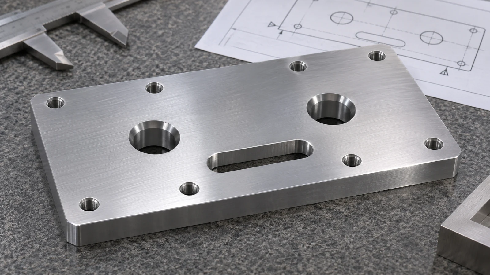
For designs with several faces or a mixture of drilled and milled features, review tool access and workholding before release. A secondary setup can introduce a relationship error between features cut from different orientations. The relevant question is whether the part can be referenced consistently—not whether every feature can be machined in one operation. See the CNC-milled bracket design guide for bracket-specific considerations.
Specify an enclosure by its openings and mounting surfaces
An equipment enclosure is more than an outside shape. Its practical interfaces include a mounting plane, cover or panel joint, connector openings, threaded holes, cable clearance and any surfaces that meet a seal. For a CNC-machined housing, show which faces are functional and how the enclosure is supported during machining and inspection. A model may show the geometry, but the drawing should make acceptance requirements explicit.
Deep pockets and thin walls can change how a housing behaves as material is removed. If a wall is flexible, the workholding force and machining sequence may affect its measured shape. Where a seal or cover depends on a continuous face, identify the sealing land and the condition in which it must be inspected. Do not assume that a machined groove or flat face alone proves a complete enclosure is sealed; sealing performance depends on the mating parts, gasket, fasteners and assembly conditions.
Choose the starting form and machining route with the actual geometry, quantity and material in view. An enclosure that needs a few controlled ports and mounting faces may be a different job from a large, deeply pocketed body. For examples of the service scope, review the CNC-milled enclosures page; confirm the specific envelope, material and finish requirements for each project.
Turn bushings, spacers and pins around their mating fits
Many auxiliary freight-train equipment assemblies use simple cylindrical interfaces: a bushing locates a shaft, a spacer sets separation, or a pin aligns two components. For these parts, the nominal diameter is only part of the requirement. Define the bore or outside diameter, shoulder position, overall length, edge break, and the mating condition that determines whether the fit is sliding, locating or fixed.
When a turned part also has a flat, cross-hole or wrench feature, show its orientation relative to the axis or a clocking datum. That relationship may require milling or drilling after turning, so the drawing should say how the feature is referenced. For multiple diameters, identify which shoulder controls assembly length and whether the dimension is measured before or after coating or another secondary operation.
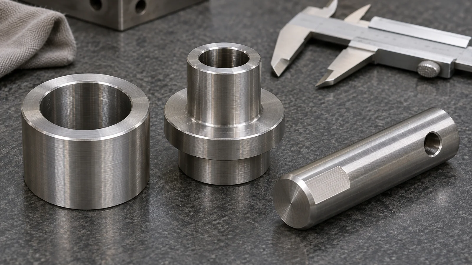
Do not use “close fit” as an acceptance requirement. State the actual fit or dimensional limits from the design authority, and identify the material and condition. A supplier can then assess the machining and inspection plan without inventing a clearance. For more on the process boundary, see CNC-turned bushings.
Choose material and finish from the environment and the drawing
Material selection should follow the component’s load, temperature, exposure, mass and mating requirements—not the assumption that every railway part needs the same alloy. The responsible designer should identify the grade, temper or other material condition, and any required documentation. If a substitution is being considered, compare the properties and the part’s actual duty before changing the specification.
Finishes also affect interfaces. Coating, plating, anodizing or paint can change dimensions, electrical contact, corrosion behavior and the fit of a bore or fastener. Mark which surfaces may be finished, which must remain masked, and whether critical dimensions are accepted before or after treatment. If the finish process is not yet selected, leave the interface open for engineering review rather than assigning an unsupported allowance.
For outdoor or vibration-exposed equipment, state the environment and the functional concern—such as corrosion exposure, loosening risk or movement at a joint—so the design and procurement teams can select suitable requirements. This is a specification discussion, not proof that a particular machined part is approved for rail service.
Inspect the part in the condition that determines fit
Inspection should follow the functional datums and the completed part condition. A bracket hole pattern may need to be checked from its mounting face; a housing bore may be related to the base or cover interface; a spacer length may be checked between the shoulders that actually contact adjacent parts. Where secondary treatment can change a critical dimension, define whether verification occurs before or after that treatment.
For a multi-feature component, agree which dimensions require recorded results and which can be checked by normal in-process methods. If a first-article report, material certificate or traceability record is required, list it in the purchase package and agree the scope before production. A generic request for “full inspection” does not identify the characteristics or records needed for acceptance.
Also resolve drawing revisions and change control. A hole pattern, connector opening or interface can change while the overall part still looks similar. Tie the order to a specific revision and make any deviation subject to written approval. That helps keep a replacement part from being judged against a different assembly definition.
What to send with a freight-train equipment part RFQ
To make a machining review useful, provide the current drawing and 3D model, material and condition, quantity, finish, critical interfaces, inspection requirements and delivery scope. Mark which dimensions control fit and which are informational. If the part mates to an existing assembly, include the relevant interface drawing or controlled dimensions rather than relying on a photograph alone.
- Part function and whether it is explicitly outside safety-critical systems.
- Drawing revision, model format, material grade and supplied condition.
- Datum scheme, hole pattern, bores, threads and mating-part requirements.
- Finish, masking areas and the dimensional state for final acceptance.
- Inspection records, traceability and any first-article requirements.
- Quantity, packaging needs and delivery destination.
Clear inputs let the supplier assess whether the bracket, enclosure or turned component fits the available CNC process and inspection scope. For a freight train equipment project, that drawing-led review is a more reliable starting point than asking for a generic “train part” quote.