
What the toolpath is doing
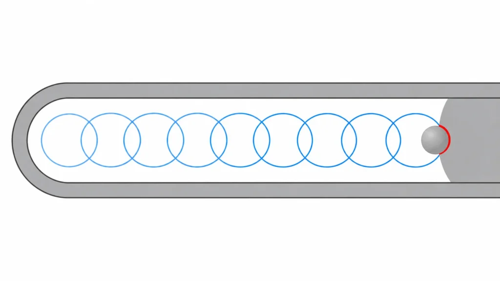 A trochoidal path combines a forward feed with repeated lateral arcs. The cutter enters and exits the material in a controlled pattern, so radial engagement is limited relative to a full-width slotting pass. Depending on the CAM strategy and feature geometry, the path may be adapted to stay within a specified engagement range or to clear a pocket in successive loops.
That description is more useful than treating “trochoidal” as a single preset. CAM systems use different algorithms and names; the programmed motion still needs review. Look at the actual path near corners, entry and exit points, narrow transitions, and remaining stock. A path that behaves well along a straight slot can create a sudden engagement spike where the geometry closes or where the tool enters a corner.
Trochoidal milling is one option within the broader Processus de fraisage CNC. The right choice should follow from feature geometry and process constraints, rather than from the label attached to a CAM operation.
A trochoidal path combines a forward feed with repeated lateral arcs. The cutter enters and exits the material in a controlled pattern, so radial engagement is limited relative to a full-width slotting pass. Depending on the CAM strategy and feature geometry, the path may be adapted to stay within a specified engagement range or to clear a pocket in successive loops.
That description is more useful than treating “trochoidal” as a single preset. CAM systems use different algorithms and names; the programmed motion still needs review. Look at the actual path near corners, entry and exit points, narrow transitions, and remaining stock. A path that behaves well along a straight slot can create a sudden engagement spike where the geometry closes or where the tool enters a corner.
Trochoidal milling is one option within the broader Processus de fraisage CNC. The right choice should follow from feature geometry and process constraints, rather than from the label attached to a CAM operation.
Where trochoidal motion earns its place
The strategy is commonly considered for deep or narrow slots, channels, and pockets where a conventional full-width pass would keep much of the cutter engaged. It can also be useful when a small cutter must clear a wider region through repeated motion, provided the toolpath maintains manageable engagement and chips can leave the cut.
It may be less compelling for a shallow, open feature that can be machined efficiently with a stable conventional path, or for a part where the extra motion increases cycle time without addressing a real load problem. Very small internal radii, fragile tool reach, a weak setup, or poor chip evacuation can limit its usefulness. Toolpath complexity cannot compensate for inadequate workholding or a machine condition that cannot follow the programmed motion consistently.
Before choosing it, describe the problem it is meant to solve: excessive radial load, long tool engagement, heat concentration, chatter, or a difficult slot geometry. If the concern is vibration, also review tool reach and the setup’s stiffness. The operation plan should be considered alongside the overall machining sequence, because roughing, rest machining, and finishing may use different strategies.
Engagement, chip load, and heat
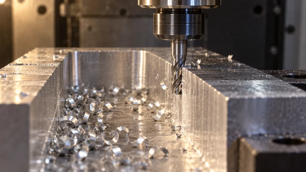 Lower radial engagement does not mean the cutting parameters can be changed blindly. Feed per tooth, spindle speed, axial depth, radial step, cutter geometry, material, and machine dynamics interact. Some high-efficiency toolpath recommendations rely on maintaining an adequate chip thickness as engagement decreases; applying a generic feed multiplier without considering the toolmaker’s guidance can overload the edge or produce rubbing instead of cutting.
Chip evacuation deserves equal attention. In a narrow slot, chips may recut if air, coolant, or the toolpath does not move them away. Recutting raises heat and can damage the cutting edge or work surface. The arc motion should provide a route for chips to clear, but the actual result depends on flute space, tool orientation, coolant delivery, slot depth, and machine enclosure conditions. Listen for changes in sound and inspect chips and the machined wall during prove-out.
Lower radial engagement does not mean the cutting parameters can be changed blindly. Feed per tooth, spindle speed, axial depth, radial step, cutter geometry, material, and machine dynamics interact. Some high-efficiency toolpath recommendations rely on maintaining an adequate chip thickness as engagement decreases; applying a generic feed multiplier without considering the toolmaker’s guidance can overload the edge or produce rubbing instead of cutting.
Chip evacuation deserves equal attention. In a narrow slot, chips may recut if air, coolant, or the toolpath does not move them away. Recutting raises heat and can damage the cutting edge or work surface. The arc motion should provide a route for chips to clear, but the actual result depends on flute space, tool orientation, coolant delivery, slot depth, and machine enclosure conditions. Listen for changes in sound and inspect chips and the machined wall during prove-out.
There is no universal parameter set for trochoidal milling. Begin with the tool manufacturer’s data and CAM guidance for the actual cutter, material, and engagement, then validate carefully on the machine. Record the conditions and observed result so a successful process can be reproduced instead of relying on a generic rule.
What must be checked before cutting
- Confirm feature geometry. Check slot width, depth, corner radii, open ends, and any intersections that may change tool engagement.
- Review cutter suitability. Consider diameter, flute count, reach, edge preparation, and whether the tool can evacuate chips from the feature.
- Inspect the programmed path. Pay attention to entries, exits, tight arcs, leftover material, and abrupt changes in engagement.
- Check machine and setup stiffness. Minimize unnecessary tool projection and support the workpiece near the cutting zone.
- Plan the rough-to-finish transition. A roughing path may leave stock that requires a separate wall or floor finishing operation.
- Prove out and measure. Monitor sound, chips, tool condition, wall quality, and the dimensions that matter to the drawing.
During prove-out, avoid changing several variables at once. If the tool chatters, determine whether the cause is engagement, reach, support, runout, or a machine limitation before increasing feed or changing the path. A measured adjustment is easier to diagnose and repeat.
Trochoidal versus conventional slotting
Conventional slotting can be straightforward and efficient when the tool, slot, and machine can tolerate the engagement and chips can clear. Trochoidal milling trades a more complex path and greater distance traveled for a different engagement pattern. Neither wins by definition. Compare the actual cycle, tool wear, surface condition, dimensional stability, and process reliability on the part feature.
For a buyer reviewing a machined slot, the important questions are not simply which CAM label was used. Ask whether the tool reached the required depth without unacceptable deflection, whether the slot width and wall condition meet the drawing, and whether the finishing plan controls the final surface. These outcomes can be assessed through the site’s de qualité et d'inspection without promising a particular toolpath for every geometry.
Frequently asked questions
Is trochoidal milling the same as high-efficiency milling?
The terms are often used in related contexts, but CAM vendors may define their strategies differently. Inspect the programmed path and engagement behavior instead of assuming that a label guarantees a particular motion or result.
Does trochoidal milling always extend tool life?
No. Reduced radial engagement may help manage load in a suitable cut, but tool life also depends on chip thickness, heat, material, cutter geometry, vibration, and chip evacuation. Recutting chips or incorrect parameters can shorten tool life.
Can it be used for finishing?
It can be used in some feature strategies, but a roughing path and a finishing path often have different goals. If wall location, size, or surface condition is critical, evaluate whether a separate finishing pass is needed.
What information is needed to evaluate a narrow slot?
Provide the drawing and 3D model, material, slot width and depth, tolerance and finish requirements, quantity, and any known access constraints. Those details help determine whether the path, cutter, and setup are suitable.