
A fixture can be rigid and repeatable yet still locate the part from the wrong reference. The central question in CNC fixture design is not “Will it clamp tightly?” but “Will it establish the intended datum without distorting the workpiece, blocking the cut, or preventing inspection?” A useful fixture plan links the drawing’s functional datums to locating points, clamp direction, tool access, and the way the finished feature will be checked.
Translate the drawing datum into locating logic
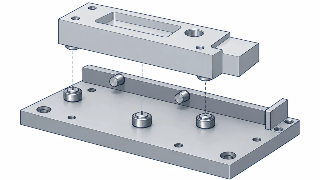 Begin with the surfaces and features that define how the component functions in assembly. A fixture should locate from those references where practical—not from a convenient but unrelated edge that merely makes the part easy to load. If a datum face is unfinished, flexible, or interrupted, determine what alternate locating scheme preserves the required relationship and how that choice will be verified.
For a prismatic part, a 3-2-1 locating concept can help organize contacts: three points establish a primary plane, two constrain a secondary direction, and one completes the location. This is a planning principle, not a universal fixture prescription. Actual contact locations must account for stiffness, surface condition, cutting forces, and the geometry of the specific workpiece.
Round or irregular parts may need a chuck, collet, V-block, profile nest, or a combination of contacts. The important outcome is controlled location with no unintended rocking. If several surfaces compete as references, identify the functional datum hierarchy on the drawing and confirm the sequence with manufacturing before finalizing the fixture.
Begin with the surfaces and features that define how the component functions in assembly. A fixture should locate from those references where practical—not from a convenient but unrelated edge that merely makes the part easy to load. If a datum face is unfinished, flexible, or interrupted, determine what alternate locating scheme preserves the required relationship and how that choice will be verified.
For a prismatic part, a 3-2-1 locating concept can help organize contacts: three points establish a primary plane, two constrain a secondary direction, and one completes the location. This is a planning principle, not a universal fixture prescription. Actual contact locations must account for stiffness, surface condition, cutting forces, and the geometry of the specific workpiece.
Round or irregular parts may need a chuck, collet, V-block, profile nest, or a combination of contacts. The important outcome is controlled location with no unintended rocking. If several surfaces compete as references, identify the functional datum hierarchy on the drawing and confirm the sequence with manufacturing before finalizing the fixture.
Design around the operation sequence
A fixture is part of the process route. It needs to hold the raw stock securely during roughing, keep the part supported as material is removed, and allow finishing passes without collisions. A setup that is excellent for the first face may be poor for a cross-hole, side pocket, or final inspection. Consider how the part will be turned or reoriented, and whether a common reference can be retained between operations.
Plan tool, holder, spindle nose, and probe clearance—not just cutter clearance. A cutter may reach a wall while the holder collides with a clamp or the fixture body. Leave space for chip evacuation and coolant where applicable; chips trapped between a locator and the part can shift the position or mar a finished surface.
Where multiple setups are unavoidable, define the datum-transfer method. It may use machined reference faces, a known bore, probing, or a dedicated nest. The sequence should state which features are established first and which later features depend on them. A process overview is available in the Guide des procédés d'usinage CNC.
Clamp without changing the part
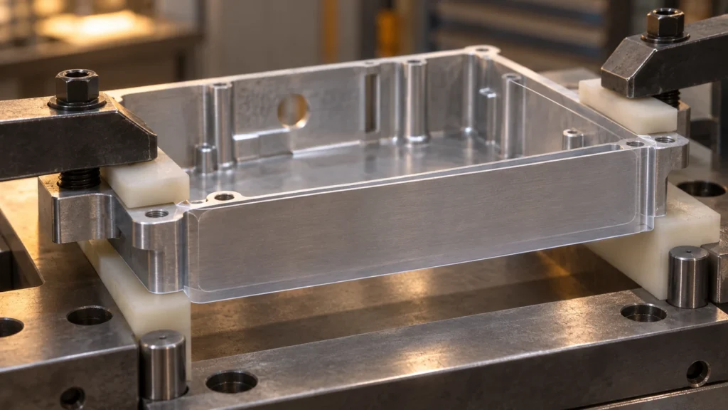 Clamping force must resist cutting loads without bending or crushing the workpiece. Thin walls, long spans, cast or stress-relieved stock, and soft materials are particularly sensitive to load location. If the part is restrained in a deflected condition and then released, the measured geometry can change. Place support near the cutting zone when possible, and distinguish support contacts from locating contacts so that the fixture does not overconstrain the part.
Use broad, stable contact where the surface allows it, but do not assume more contact is always better. A high point, burr, or chip can create a false seat. Clamp sequence matters too: tightening one point fully before the others can pull a part away from its intended datum. Consider controlled stops, equalized clamping, or a sequence that seats the workpiece before applying full force.
For parts with delicate or finished surfaces, specify pads or protective interfaces only when their behavior is understood. A compliant pad can protect a surface but may introduce movement or repeatability variation. The fixture should also make loading orientation obvious; an asymmetric nest or clear orientation feature can prevent an operator from placing the part in a plausible but wrong position.
Clamping force must resist cutting loads without bending or crushing the workpiece. Thin walls, long spans, cast or stress-relieved stock, and soft materials are particularly sensitive to load location. If the part is restrained in a deflected condition and then released, the measured geometry can change. Place support near the cutting zone when possible, and distinguish support contacts from locating contacts so that the fixture does not overconstrain the part.
Use broad, stable contact where the surface allows it, but do not assume more contact is always better. A high point, burr, or chip can create a false seat. Clamp sequence matters too: tightening one point fully before the others can pull a part away from its intended datum. Consider controlled stops, equalized clamping, or a sequence that seats the workpiece before applying full force.
For parts with delicate or finished surfaces, specify pads or protective interfaces only when their behavior is understood. A compliant pad can protect a surface but may introduce movement or repeatability variation. The fixture should also make loading orientation obvious; an asymmetric nest or clear orientation feature can prevent an operator from placing the part in a plausible but wrong position.
Build verification into the fixture concept
Ask how the first part will be checked while the setup is still being designed. Can critical features be probed in the fixture, or must the part be removed and re-established on a CMM? Does the fixture block a datum face needed for inspection? If in-process measurement is planned, define how the machine coordinate system relates to the drawing datums and how offsets are controlled.
A fixture that repeats its own position does not prove that the part is located correctly relative to the drawing. Verification should connect the fixture’s locating scheme to measurable part features. For production work, the plan may include first-piece approval, periodic checks, and a final inspection report; the required method depends on the drawing and buyer’s acceptance requirements.
If the design includes tight positional or profile controls, ensure the inspection approach is practical and agreed. The related CNC quality-control overview discusses how process checks and final acceptance fit together.
Fixture review questions
- Which drawing datum does each locator establish, and what prevents rocking?
- Where do cutting forces act, and how is the part supported near that load?
- Can the cutter, holder, probe, and chips reach or clear every required area?
- Will clamping deform a thin feature or mark a finished surface?
- How does each later setup recover the earlier datum relationships?
- Can the key dimensions be inspected without changing the reference condition?
The answer does not need to be a complex custom fixture for every part. A vise, chuck, collet, or standard locating element may be appropriate when it satisfies the same requirements. Fixture design is successful when the locating logic is traceable, the part remains stable through the planned operations, and the resulting features can be verified against the drawing.
Frequently asked questions
Does a more rigid fixture always produce better accuracy?
Rigidity helps resist cutting loads, but accuracy also depends on locating references, clamp-induced distortion, datum transfer, machine condition, and inspection. Excessive or poorly placed force can reduce accuracy.
Should the fixture use the drawing datum surfaces?
Where practical, yes. If the datum surface is unsuitable, the alternate locating method should preserve the intended functional relationship and be verifiable.
Can one fixture support every operation?
Sometimes, but not always. Tool access, part orientation, clamping, and inspection can require additional setups. A controlled transfer scheme is more important than forcing a single setup.
When should fixture design be reviewed?
Review it during process planning, before production programming is finalized. Early review can expose access, clamping, and datum questions while drawing or sequence changes remain practical.