
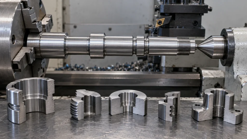
Processus de tournage CNC la planification repose sur un fait physique : la pièce tourne tandis qu'un outil de coupe contrôle les diamètres, les épaulements, les gorges, les alésages et les filetages. Cela fait du tournage une solution idéale pour les pièces dont les caractéristiques importantes partagent un axe central, mais un raccourci médiocre pour une géométrie nécessitant un accès sur une large face ou plusieurs caractéristiques hors axe. Ce guide montre comment choisir une gamme de tournage à partir des surfaces fonctionnelles de la pièce, du rapport longueur-diamètre, du matériau, du maintien en position, des besoins d'inspection et de la quantité de production. Pour la séquence plus large allant de la CAO à la pièce finie, voir le Aperçu du processus d'usinage CNC.
Pourquoi la géométrie centrée sur l'axe modifie le processus
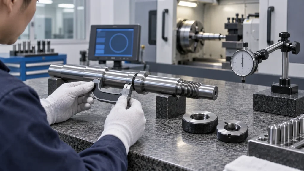
Les pièces tournées typiques comprennent les arbres, les goupilles, les bagues, les entretoises, les raccords, les tiges de soupape, les corps de connecteur, les buses et les composants filetés. Le processus devient moins simple lorsqu'une pièce semble ronde mais contient également des trous latéraux, des méplats, des rainures ou des caractéristiques de montage. Ces caractéristiques peuvent nécessiter de l'outillage motorisé, une contre-broche, un centre de tournage-fraisage ou une autre opération planifiée.
La sélection du procédé doit suivre la carte des caractéristiques. Un diamètre extérieur rond ne suffit pas à justifier le tournage si la fonction critique de la pièce dépend d'une relation hors axe que le tour ne peut atteindre ou inspecter de manière fiable.
Commencer par le brut, la longueur et le support
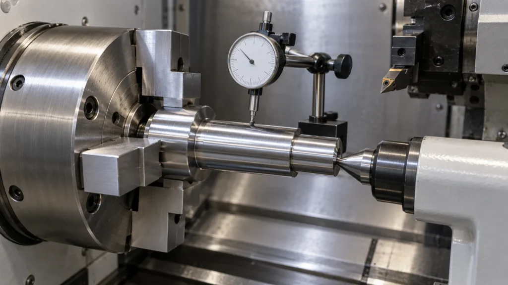
Comment le rapport longueur-diamètre affecte-t-il le risque ?
Un brut long et élancé est plus sensible à la déflexion, aux vibrations, à la chaleur et à la pression de coupe. La longueur non supportée, le serrage par mandrin ou pince, le support de contre-pointe, les lunettes, les douilles de guidage et l'ordre d'enlèvement de matière influencent tous la stabilité de l'axe fini. Une coupe profonde acceptable sur une pièce courte et rigide peut créer des marques de broutage ou un cône sur un arbre long.
Le support doit être planifié en fonction de la géométrie finale, et non uniquement du brut de départ. Enlever un grand diamètre trop tôt peut affaiblir la pièce avant qu'un petit diamètre ou un filetage ne soit terminé. Conserver une portée de support jusqu'à une étape tardive de la séquence peut protéger la rectitude et réduire le besoin de passes correctives agressives.
Quels détails du brut doivent figurer dans la demande de prix ?
Indiquez la nuance de matière, l'état, la préférence pour la barre ou le tube, le diamètre de départ, la longueur de coupe, les besoins de certification et la quantité prévue. Si une pièce est produite à partir d'une pièce moulée ou forgée, incluez l'état fourni et tout surépaisseur d'usinage. Des informations manquantes sur le brut peuvent fausser à la fois le procédé chiffré et le rendement matière attendu.
Construire la séquence de tournage autour de la stabilité
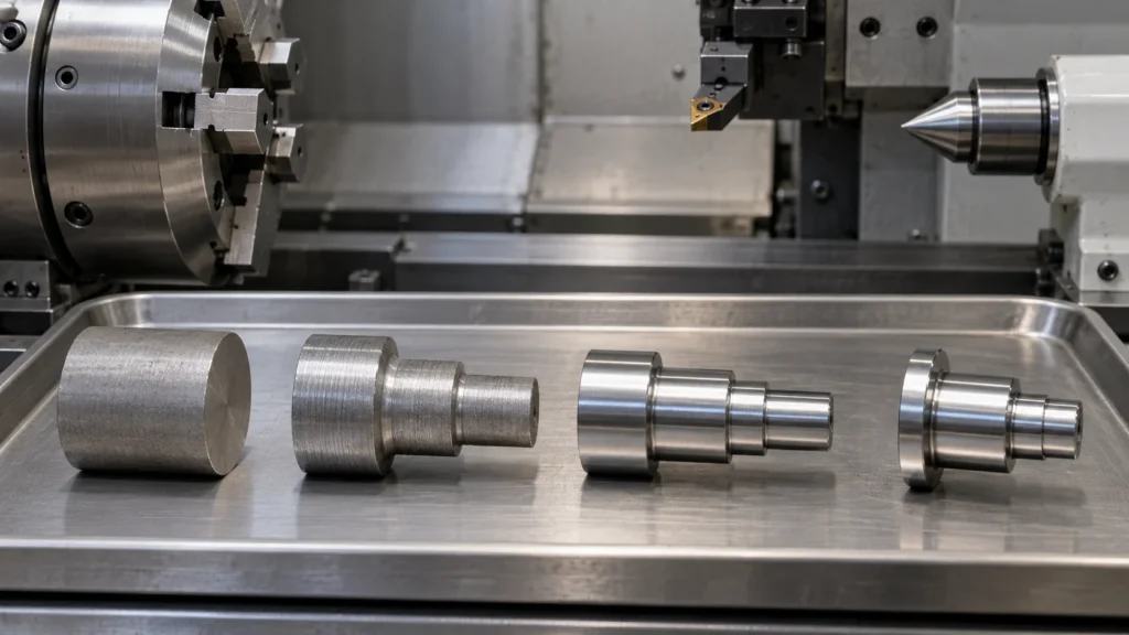
| Étape du procédé | Objectif principal | Risque à gérer |
|---|---|---|
| Dressage et création de référence | Établir une surface d'extrémité et un point de départ contrôlé | Mauvais appui, faux rond ou décalage d'origine incorrect |
| Ébauche au tour | Remove material efficiently while retaining support | Deflection, heat, chip control, and excessive tool load |
| Finish turning | Create final diameters, shoulders, tapers, and surface condition | Tool wear, vibration, residual stress, and thermal drift |
| Parting and secondary work | Separate the component or complete back-end features | Burrs, weak support, back-end runout, and handling damage |
The most economical sequence is not always the one with the fewest tool changes. A stable sequence that avoids rework, protects a locating surface, and produces a measurable first article can lower total cost more effectively than a nominally shorter cycle.
Sélectionner les opérations pour les caractéristiques requises
Turning operations should be selected by feature function. Straight turning controls an outside diameter. Facing creates a flat end. Boring refines an internal diameter. Grooving creates a relief or retaining feature. Threading generates the specified internal or external connection, and parting separates the component from the remaining stock.
What makes a turned feature easy to control?
- Diameter, bore, shoulder, and thread features share a practical spindle axis.
- Tool access is clear and does not require excessive reach or unsupported cutting.
- Drawing datums match the surfaces used to locate the part in the chuck, collet, or fixture.
- Critical diameters have enough stock for a stable finishing pass.
- Grooves, reliefs, radii, and thread runouts give the tool a controlled exit condition.
Threads deserve their own callouts. Identify the standard, size, fit or class where applicable, depth, starting chamfer, sealing function, and gauge requirement. A nominal thread note without a clear use case can still leave the supplier uncertain about inspection and finishing.
Adapter les outils et les conditions de coupe au matériau
Tool geometry, insert grade, nose radius, speed, feed, depth of cut, coolant, and chip evacuation should match the material and the feature. Ductile materials may produce long chips or built-up edge. Hardened or work-hardening materials can increase heat and tool wear. Plastics may deform under heat or clamping instead of behaving like a metal workpiece.
Material grade and condition should be confirmed before programming. The site’s CNC turning materials information can support early route discussions, but final cutting conditions still depend on the machine, tooling, geometry, stock, and required surface.
Chasing maximum removal rate can create a bad trade. If tool pressure bends a slender part or heat shifts a critical diameter, the apparent cycle-time gain is lost in rework. Good turning balances productivity with rigidity, repeatability, and inspection evidence.
Garder le faux-rond et le transfert de référence sous contrôle
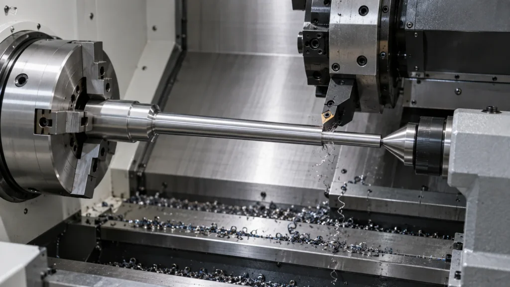
When the reverse end is completed in a second operation, the transfer method becomes part of the tolerance stack. Define which diameter or face is used for re-location, how runout is checked, and which relationships must be verified after the second chucking. If cross-holes or flats are required, live tooling or a turn-mill route may reduce the number of transfers.
Savoir quand l'outillage motorisé ou un second processus est nécessaire
Standard turning is efficient when the part is primarily rotational. A component with side holes, milled flats, slots, or off-axis features may need live tooling, a sub-spindle, or a dedicated mill operation. Combining features in one machine can reduce transfer risk, but the route may require more programming, tooling, and collision verification.
Review the supplier’s CNC turning capability against the drawing, then confirm whether the part should remain on a turning center or move to a turn-mill workflow. Process choice should be based on access and relationships, not on the assumption that one machine type is always superior.
Inspecter les relations qui contrôlent l'ajustement
- Verify material identity and required certification.
- Measure critical outside diameters, bores, shoulders, grooves, and lengths.
- Check thread size, depth, fit, gauge result, and sealing condition.
- Evaluate runout, concentricity, perpendicularity, and reverse-operation relationships.
- Inspect burrs, chips, surface condition, cleaning, and packaging protection.
Use the required measurement method rather than adding a generic “100% inspected” statement. For complex relationships, coordinate measurement or a defined gauge plan may be appropriate. Supplier quality expectations can be aligned with the CNC quality management information.
Préparer une demande de devis de tournage qui peut être chiffrée
Send the latest CAD model and controlled drawing with part number, revision, quantity, forecast, material, stock preference, thread standards, surface requirements, and delivery expectations. Mark the features that control assembly, sealing, rotation, pressure, or alignment.
- Identify primary and secondary datums and the surfaces used for chucking or re-location.
- State length-to-diameter concerns, unsupported lengths, thin sections, and required support.
- Define threads, grooves, bores, fits, runout, concentricity, and surface requirements.
- List live-tooling features, back-end operations, coating, passivation, polishing, or cleaning.
- Specify first-article, sampling, gauge, CMM, material-traceability, and packaging documents.
FAQ sur le processus de tournage CNC
What parts are best suited to CNC turning?
CNC turning suits shafts, pins, bushings, fittings, sleeves, valve stems, threaded bodies, and other parts whose primary features are rotational or concentric about a centerline.
What is the difference between CNC turning and CNC milling?
Turning rotates the workpiece and uses tools to create rotational features. Milling generally holds the workpiece on a table or fixture while a rotating cutter creates faces, pockets, slots, holes, and profiles. Parts with both feature families may require turn-mill machining.
Why do long turned parts chatter or taper?
Long parts are more sensitive to deflection, vibration, heat, tool pressure, and insufficient support. Stock support, tool reach, workholding, cutting conditions, and the order of material removal all affect stability.
Can CNC turning produce threads and bores?
Yes. CNC turning can produce many internal and external threads, bores, grooves, shoulders, tapers, and diameters when the drawing defines the required standard, fit, depth, and inspection method.
When should a turned part use live tooling?
Live tooling is useful when a rotational part also needs cross-holes, flats, slots, or other off-axis features. The decision depends on access, quantity, setup risk, tolerance relationships, and the cost of a separate milling operation.
Reliable turning comes from matching centerline geometry, stock support, tool sequence, workholding, material behavior, and inspection. When those decisions are made before the first cut, a turning center can deliver repeatable diameters and relationships without hiding risk inside the setup.