
Start with the part, not the clamp
Before selecting a vise, chuck, fixture plate, or custom nest, identify the surfaces that establish the part’s position. These are the datums the setup must locate and protect. Then mark the material to remove, the surfaces that tools must reach, and the areas where a clamp can safely apply force. This simple map often rules out a seemingly convenient setup: a jaw may cover a bore, a strap clamp may obstruct a finishing pass, or a thin wall may deflect when force is applied across it.
Geometry and process stage matter together. A roughing setup must resist interrupted or changing cutting loads while leaving stock for finishing. A finishing setup may need lower, more uniform restraint to avoid spring-back after release. For a part requiring multiple orientations, ask whether the next setup can locate from finished datums rather than from rough stock. A good workholding plan controls the relationship between operations; it does not merely keep the workpiece from moving.
Drawings should make critical relationships explicit. If a hole pattern, bearing fit, sealing face, or datum-to-datum relationship drives function, identify it for inspection and setup planning. General dimensions alone may not tell the machinist which face should locate first. For broader process context, see the CNC-Bearbeitungsprozess guide.
How common workholding methods differ
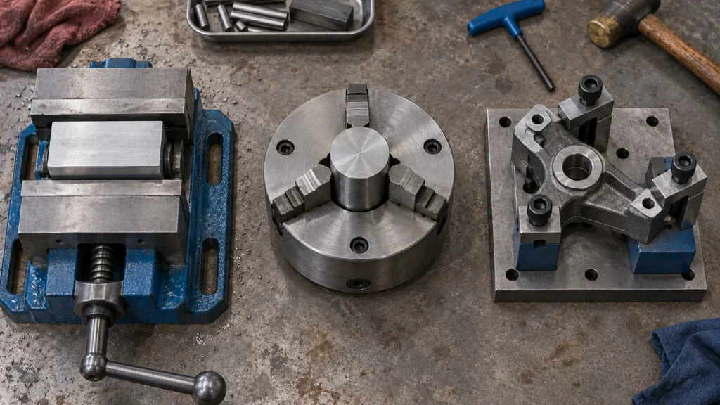 Each method solves a different combination of shape, access, and repeatability. The table is a screening aid, not a universal ranking; actual suitability depends on part dimensions, machine configuration, tooling, and the operation sequence.
Vise workholding is not automatically the low-cost choice if the part needs several re-clamps to reach its features. A custom fixture is not automatically better if the quantity is small and the fixture takes substantial design and prove-out effort. Compare the complete setup plan, including loading, locating, cutting access, and inspection—not only the first clamping action.
Check the load path and access
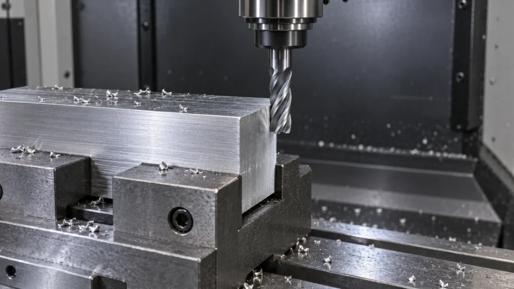 Cutting forces travel from the tool through the workpiece into the locating contacts, clamps, fixture body, and machine table. If that path is long, flexible, or poorly supported, the part can vibrate or deflect even when the clamp feels tight. Place support near the region being machined when practical, especially beneath thin plates or tall features. Do not use additional force to compensate for a weak support arrangement; excessive clamping can distort the part before the cut begins.
Tool access is the other half of the decision. A setup that grips securely but blocks the cutter, holder, or probe may force an extra orientation or a longer tool. Longer reach can increase deflection and reduce stability. Consider the full tool assembly and the approach direction, not just the cutter diameter. If machining several faces, a fixture may provide useful access, but it also needs adequate clearance for chips, coolant, probing, and safe loading.
For milling-specific access and operation planning, the CNC-Fräsprozess overview provides related context. The final arrangement should let the tool reach the intended surface while preserving a stable, inspectable datum reference.
Cutting forces travel from the tool through the workpiece into the locating contacts, clamps, fixture body, and machine table. If that path is long, flexible, or poorly supported, the part can vibrate or deflect even when the clamp feels tight. Place support near the region being machined when practical, especially beneath thin plates or tall features. Do not use additional force to compensate for a weak support arrangement; excessive clamping can distort the part before the cut begins.
Tool access is the other half of the decision. A setup that grips securely but blocks the cutter, holder, or probe may force an extra orientation or a longer tool. Longer reach can increase deflection and reduce stability. Consider the full tool assembly and the approach direction, not just the cutter diameter. If machining several faces, a fixture may provide useful access, but it also needs adequate clearance for chips, coolant, probing, and safe loading.
For milling-specific access and operation planning, the CNC-Fräsprozess overview provides related context. The final arrangement should let the tool reach the intended surface while preserving a stable, inspectable datum reference.
Repeatability changes the decision
A one-off prototype and a recurring production order do not carry the same workholding economics. For a single part, a standard vise or adaptable fixture may avoid investment in a dedicated device. As repeat quantity rises, loading time, operator variation, orientation changes, and setup verification can become more important than the fixture’s initial design effort.
Repeatability comes from a controlled locating sequence, clean contact surfaces, consistent clamping, and a way to detect incorrect loading. Stops, pins, pockets, or shaped jaws may help, but only when their relationship to the part datums is clear and maintained. Chips trapped under a part can shift its height; a worn stop can move a repeated feature; uneven force can distort a thin section. A fixture should make the correct setup natural and make common loading errors visible.
For multi-operation work, document which surfaces are used in each setup and how the next operation references the previous one. In-process checks should target the dimensions most sensitive to setup movement. That is where workholding planning connects directly with the site’s quality approach: the inspection plan should verify the relationships that the setup is intended to preserve.
A practical selection sequence
- Identify the datum surfaces. Separate functional datums from surfaces that are merely convenient to grip.
- Mark tool and probe access. Include holder clearance, approach direction, and any required inspection orientation.
- Estimate the cutting load and part stiffness. Pay particular attention to thin walls, tall features, narrow bridges, and interrupted cuts.
- Choose the simplest method that satisfies the constraints. Compare a standard vise or chuck with soft jaws, clamps, or a dedicated fixture.
- Plan each setup transition. Define how the part is re-located and which dimensions confirm that the transition worked.
- Review total effort. Include loading time, changeover, fixture preparation, inspection, and likely repeat quantity.
This sequence prevents two common mistakes: designing a fixture before confirming the machining sequence, and selecting a clamp based only on its holding force. The goal is a stable, accessible, and verifiable setup that fits the part’s actual production context.
Frequently asked questions
Is a vise always the best choice for a CNC-milled part?
No. A vise is convenient for many prismatic parts, but may obstruct features, provide poor support, or require repeated reorientation. Compare access and datum control with the complete operation sequence.
When should a dedicated fixture be considered?
Consider one when geometry is difficult to locate consistently, several parts are machined in a repeat cycle, or a fixture can materially reduce setup variation. For low quantities, first compare its design and prove-out effort with an adaptable setup.
Can clamping force change the finished dimensions?
Yes. Thin or flexible sections can deform under clamping and relax after release. Support the part near the cutting zone and use a controlled, suitable force rather than assuming tighter is safer.
What information helps a shop evaluate workholding?
Provide the 3D model and drawing, material and stock condition, critical datums and tolerances, required quantities, surface-finish needs, and any known assembly or inspection requirements. This lets the setup be considered alongside the machining plan.