
A shaft keyway drawing should control more than the slot width. To produce a key that seats and transmits torque as intended, the specification must identify the applicable key/keyseat standard or custom geometry, keyway width and depth, its angular and axial location, the fit relationship, and the datum used to inspect it. The shaft diameter alone does not define every keyseat requirement, and a standard table should not be treated as a substitute for the assembly’s actual design intent. Start with the mating hub and key, then state which dimensions come from the selected standard and which are project-specific. Finally, define the inspection method so the supplier can verify the slot without confusing depth from the shaft surface with depth from the opposite side of the seat.
Select the key and governing standard
Identify whether the design uses a parallel key, taper key, or a special arrangement. The applicable standard establishes relationships among shaft diameter, key size and keyseat geometry within its scope. ASME B17.1, for example, covers sizes and tolerances for parallel and taper keys and keyseats, while noting that its standard dimensions are intended for single-key applications. Confirm the current contractual edition and the design’s number of keys before using its tables.
A standard selection does not automatically settle the torque capacity, hub length, material strength, fatigue life, or fit for every assembly. Those decisions depend on loading, materials, geometry and the design method. The drawing should name the standard and revision or provide the complete custom dimensions rather than relying on an ambiguous note such as “standard keyway.”
Specify width, depth, and fit intent
Keyway width controls the side fit between key and seat; depth affects the radial engagement and the remaining shaft section. The hub seat and shaft seat are related but not identical features. A drawing should distinguish shaft-seat depth from the dimension used to locate the keyway floor relative to the shaft’s opposite surface. This distinction matters when checking the key height above the shaft and the clearance inside the hub.
State the limits and fit class that apply to the key and keyseat. Do not add a tight width tolerance without considering the mating key, hub slot, assembly method and intended load sharing. The fit should be selected by the responsible designer using the governing standard or calculation, not inferred from a machinist’s customary practice.
| Callout item | Why it matters |
|---|---|
| Key and keyseat type/standard | Defines the basic geometry and fit convention |
| Slot width and tolerance | Controls side clearance or interference with the mating key |
| Seat depth reference | Prevents confusion between surface depth and opposite-side location |
| Length and end condition | Defines usable engagement and how the key terminates |
| Position datum and angular orientation | Relates the keyway to shoulders, holes, flats or other features |
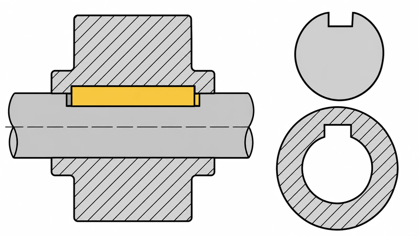
Locate the slot from functional datums
Dimension the keyway’s axial position from the shoulder or end feature that locates the hub. Define its angular orientation from a datum flat, cross-hole, spline, or another functional reference if orientation matters during assembly. If there is no angular requirement beyond a single key, say how the slot is clocked relative to the datum axis or drawing view.
Consider how the shaft will be held during turning and milling. If the keyway must remain aligned with a cross-hole or another milled feature, a common datum structure or a controlled transfer between setups is needed. Avoid chains of dimensions that make the final relationship depend on several independent tolerances when one direct functional dimension would be clearer.
For related shaft geometry, review the site’s machined shafts and CNC turning pages. The actual process route must follow the part’s configuration and access.
Plan machining and inspection together
External shaft keyways can be milled with the shaft supported and indexed to the required orientation. Internal keyseats in hubs may use a different process, such as broaching or EDM, depending on geometry, quantity and access. This article focuses on defining the feature; it does not imply that one process is suitable for every design. Identify corner radii and end relief where they affect the key, assembly or stress concentration, and avoid applying a broad edge-break note to the functional seat edges without review.
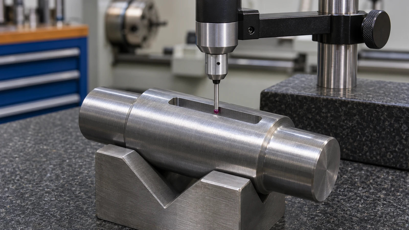
Inspection should cover width, depth, length and position with instruments or gauges suited to the feature. A pin or key can provide a functional check only if its dimensions and fit are controlled. If the keyway is difficult to probe directly, agree on the measurement method and reference before production. Inspect the key and mating hub as well as the shaft when fit is the acceptance concern.
Deburring must remove raised edges without rounding the seat or changing its width. Surface finish and burr limits should be called out where they affect seating or assembly; they should not be expanded into arbitrary requirements on nonfunctional surfaces.
Release a keyway definition that can be checked
A complete release package includes the shaft and hub interface, key type and material if specified, governing standard and edition, keyway dimensions and limits, datums and orientation, edge treatment, inspection method, and any assembly acceptance check. If a standard table is used, state which features are standard and which have been modified. Record the drawing revision so a future supplier can reproduce the approved interpretation.
When reviewing a supplier question, distinguish a true design change from a clarification of the measurement reference. A proposal to alter width, depth or fit can affect load transfer and assembly. Resolve it with the design authority, update the controlled drawing when approved, and keep the inspection report tied to that revision.