
CNC hole and shaft fit design should begin with the assembly job, not with a familiar letter-number fit copied from another project. A sliding guide, locating pin, press-fit bushing, bearing seat, and sealed diameter all need different clearance, surface, and inspection decisions. The hole and shaft must be treated as one functional pair, including material, temperature, coating, lubrication, assembly force, and the condition after finishing.
Fit Selection in One View
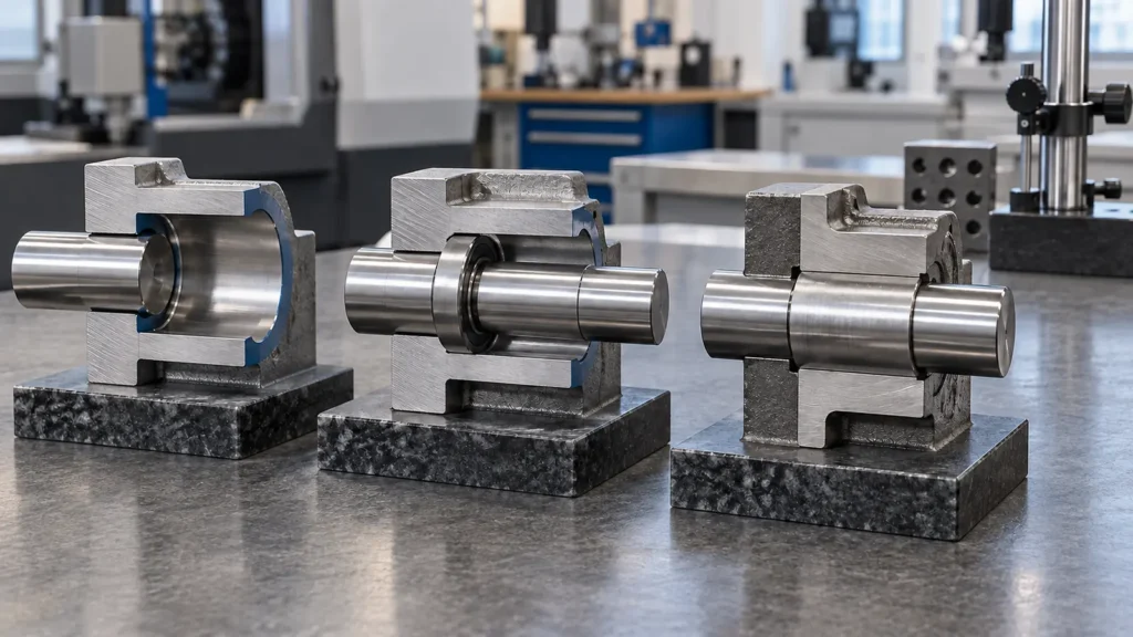
Translate the assembly into a fit requirement
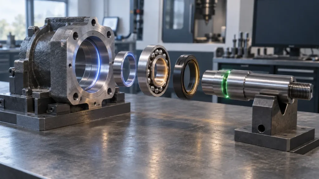
| Assembly job | Typical fit direction | Design questions |
|---|---|---|
| Guided sliding motion | Controlled clearance | What speed, load, lubrication, and contamination are expected? |
| Repeatable locating pin | Small clearance or transition | How often is the joint assembled, and which member is replaceable? |
| Permanent bushing or insert | Interference or controlled press fit | What wall thickness, insertion force, and service temperature apply? |
| Bearing seat | Fit selected by ring load and service condition | Which ring rotates, and how are runout, shoulder, and surface finish controlled? |
The same nominal diameter can need very different limits in these applications. A fit that is acceptable for a removable cover may be too loose for a locating pin and too tight for a thin-walled housing. Write the functional requirement before selecting a standard class.
Choose clearance, transition, or interference
A clearance fit keeps the smallest hole larger than the largest shaft, so movement or easy assembly is expected. A transition fit can produce either small clearance or light interference, depending on the actual limits. An interference fit keeps the shaft larger than the hole and relies on elastic deformation, insertion force, heating, cooling, or a combination.
Clearance is a performance window
Too little clearance can cause seizure after temperature rise, coating, contamination, or misalignment. Too much clearance can create noise, wobble, leakage, or poor positional repeatability. The useful specification is the range that protects the real interface across its operating conditions.
Interference is also a stress calculation
A press fit does not only hold the shaft. It loads the surrounding material. Thin hubs, brittle materials, interrupted bores, sharp edges, and cross-holes can crack, distort, or lose roundness during assembly. Define the allowable assembly method and inspect the finished relationship, not only the two free-state diameters.
Use a hole-basis or shaft-basis system
A hole-basis system keeps the basic hole condition consistent and changes the shaft tolerance to create the required fit. A shaft-basis system keeps the shaft condition consistent and changes the hole tolerance. Neither system is universally better; the choice depends on standard tooling, replaceable components, process capability, and the rest of the assembly.
- Prefer hole basis when standard drills, reamers, broaches, or bearing bores make the hole the more economical reference.
- Prefer shaft basis when a standard shaft, ground bar, or common external diameter must remain unchanged across several mating parts.
- Use explicit limits when the project depends on a custom clearance, a coating allowance, or a material combination that a generic fit class does not describe well.
The drawing should state the selected system, size range, units, and whether the fit applies before or after finishing. Do not leave a supplier to infer whether a letter-number designation controls the machined condition, coated condition, or final assembly condition.
Allow for material and surface conditions
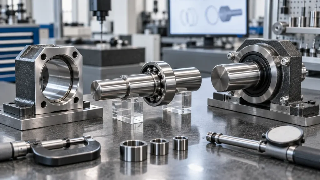
| Condition | Possible fit change | Planning response |
|---|---|---|
| Different operating temperatures | Hole and shaft grow at different rates | Evaluate the fit at the service temperature, not only at room temperature |
| Anodizing, plating, or coating | Surface build changes both mating dimensions | Call out thickness, masking, allowance, and post-finish inspection |
| Lubrication or contamination | Friction and insertion force change | Define cleanliness, lubricant, and assembly condition |
| Flexible or moisture-sensitive material | Free-state size can shift after machining or storage | Define conditioning, support, measurement timing, and functional allowance |
Make the fit machinable and inspectable
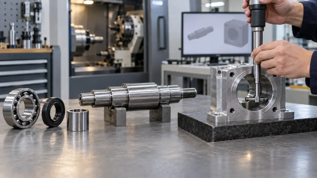
Protect the mating surfaces
A burr, torn edge, raised grain, or coating build-up can prevent a fit from behaving as the dimensions suggest. Specify edge treatment where it affects insertion, sealing, or seating. Surface finish should be tied to friction, wear, leakage, or appearance rather than added as an unexplained low number.
Avoid promising a universal tolerance
A practical fit depends on diameter, length, material, geometry, setup, and inspection method. The site’s CNC machining tolerances guide provides the broader tolerance-planning context; the fit drawing still needs its own limits and functional acceptance condition.
Verify the pair, not isolated dimensions
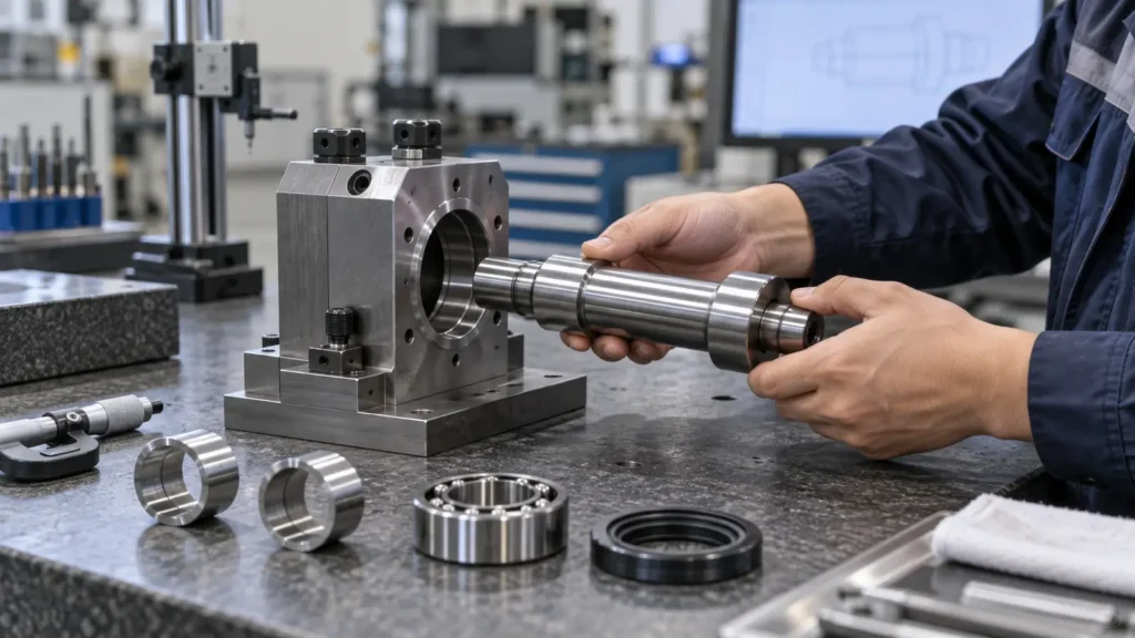
- Confirm the material, heat treatment, coating, and inspection temperature.
- Measure the hole and shaft with calibrated methods appropriate to their size and geometry.
- Check roundness, straightness, runout, shoulder contact, and burr condition when the function depends on them.
- Record the actual mating limits and confirm assembly force, motion, or locating performance when required.
When inspection planning is critical, align the acceptance method with the supplier’s quality and inspection process. A fit is a relationship, so the report should make the relationship visible.
Hole and shaft fit FAQs
Should I specify a fit class or actual limits?
Use a recognized fit system when it clearly communicates the function and size range. Add actual limits or supplementary notes when coating, temperature, material, lubrication, or a custom assembly condition makes the standard designation incomplete.
Is a press fit suitable for every material?
No. The interference that works in a ductile metal hub may crack a brittle material, distort a thin wall, or permanently deform a plastic. Review material strength, wall thickness, temperature, insertion method, and service loads before selecting the interference.
Does surface finish affect a hole and shaft fit?
Yes. Roughness, waviness, burrs, polishing, plating, and anodizing can change effective size and friction. State the final surface condition and measure the critical mating features after the finishing step that affects assembly.
Why can two parts pass diameter inspection but fail assembly?
Axis tilt, runout, out-of-roundness, burrs, poor shoulder contact, temperature, or coating build-up can prevent assembly even when a single diameter is acceptable. Functional inspection should include the geometric relationships that control the joint.
What should be included in a fit-focused RFQ?
Include the controlled drawing, CAD model, material and condition, quantity, fit intent, operating temperature, finish, lubrication or cleanliness requirement, assembly method, critical datums, and inspection evidence expected. This lets the supplier review the pair rather than quote two unrelated features.