
When a filled PEEK part wears cutters faster than expected, the first question is often whether carbon-fiber-reinforced CF30 or glass-fiber-reinforced GF30 is the better stock choice. The answer is not simply “carbon is better” or “glass is cheaper.” Both are reinforced engineering plastics, and their fibers can change cutting behavior, edge quality, dimensional response, and the finished part’s functional properties. Select the grade around the component’s duty and the machining evidence, not around tool life alone.
Contents
- Start by locating the wear problem
- How the reinforcement changes cutting
- Connect wear to part geometry and acceptance
- Choose the grade from the application
- Run a controlled machining comparison
- FAQ
Start by locating the wear problem
Before changing material, identify what “tool wear” means in the current process. Is the edge rounding quickly, chipping, leaving a rough surface, or building up residue? Does the issue appear during facing, slotting, drilling, or finishing? Is it limited to one tool position or one feature? A photo of the edge, the operation sequence, and inspection results are more useful than a general report that the plastic is abrasive.
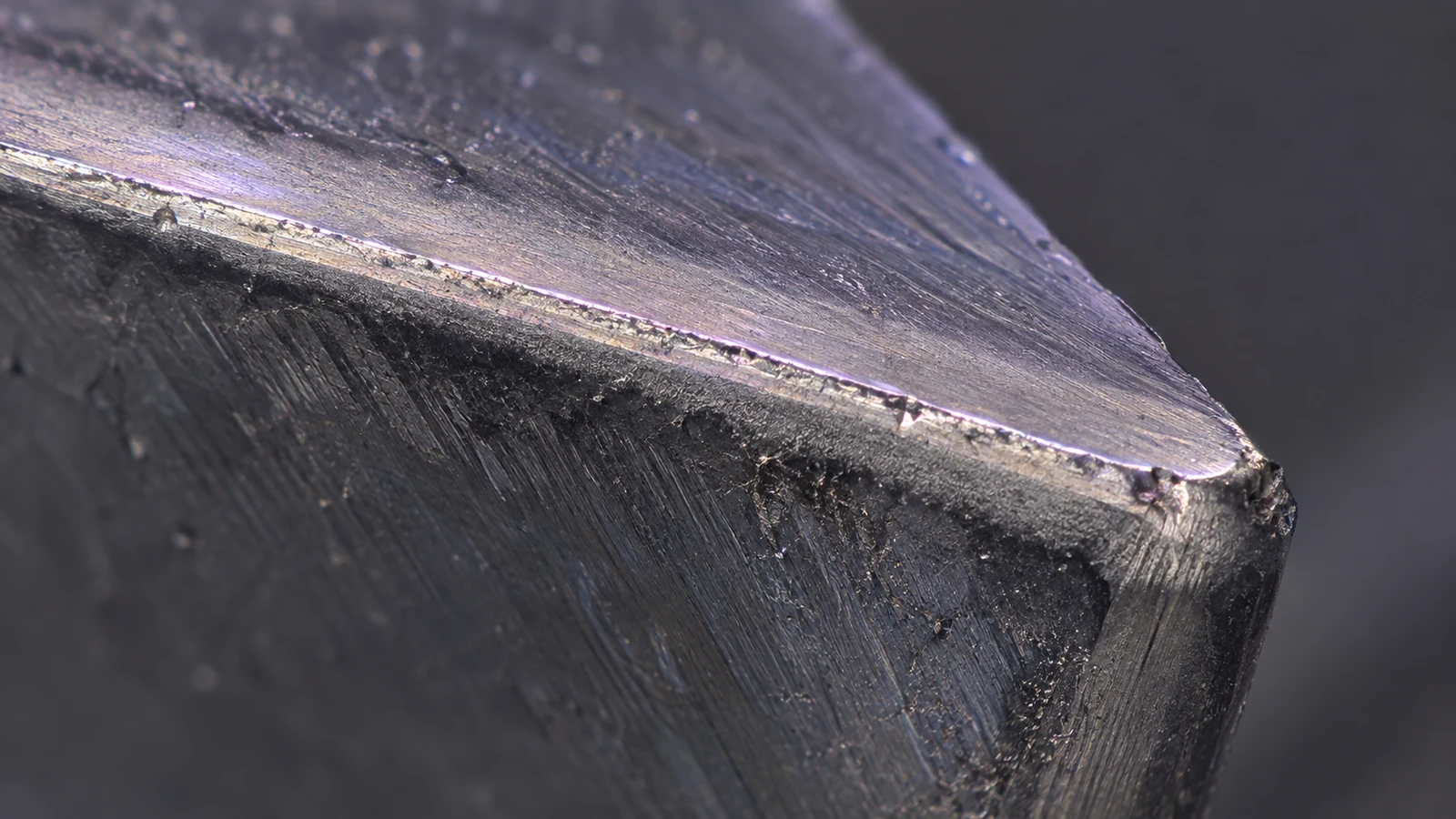
Check whether the tool actually reaches its life limit or whether another issue is being interpreted as wear. A dull-looking edge can coincide with runout, poor chip evacuation, a damaged insert, excessive engagement, or inconsistent stock. Record the cutter material and geometry, edge preparation, cutting path, workholding, coolant or air strategy, and the number of parts produced before quality shifts. Keep the stock supplier, grade designation, and lot traceable during the comparison.
The site’s CF30 PEEK information and GF30 PEEK information are starting points for identifying the grades. Confirm the supplier’s exact product and current technical data; grade names alone do not establish identical fiber content, condition, or properties across manufacturers.
How the reinforcement changes cutting
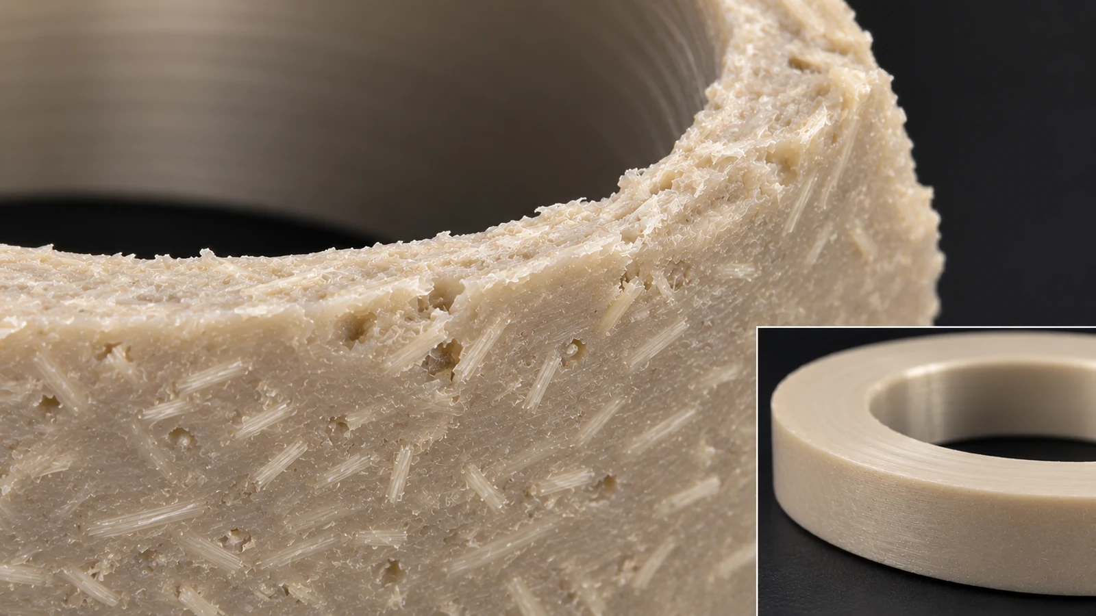
Carbon and glass reinforcement can both increase tool wear relative to unfilled PEEK, but the wear pattern depends on the specific grade, cutter, and operation. Fibers exposed at a machined surface may contribute to abrasion and a different edge texture. The direction and distribution of reinforcement can also affect how a cut exits the material. This is why the same cutter may produce different results in a broad face mill and a small drilled cross-hole.
CF30 is frequently considered when stiffness, strength-to-weight, or dimensional behavior are important design goals. GF30 may be selected for a different balance of mechanical and cost requirements. Those broad descriptions are not a substitute for comparing the actual datasheets and part requirements. A grade chosen for a property the part does not use may add cost and machining burden without improving function.
Machining parameters should not be copied from a generic plastics chart without confirming the machine and tool. Cutting speed, feed, engagement, tool sharpness, and chip removal interact. Excessive heat can affect the workpiece and edge condition; an unsuitable feed can rub rather than cut cleanly. Establish a stable baseline, change one variable at a time, and review the actual surface and dimensions after the part returns to temperature.
Connect wear to part geometry and acceptance
Geometry determines where reinforcement-related effects become visible. Thin walls can move under clamping or cutting force. A deep pocket can retain chips or restrict airflow. Small holes may show a different exit edge than a broad milled face. A sealing land, bearing fit, or cosmetic surface may have a stricter acceptance requirement than a nonfunctional wall. If the drawing does not identify a critical edge or finish, agree on what is acceptable before comparing grades.
| Observed issue | First process checks | Material question |
|---|---|---|
| Rapid edge rounding | Tool material, edge condition, engagement, lot traceability | Does the grade or reinforcement differ from the qualified stock? |
| Fuzzy or raised fibers | Sharpness, exit direction, finishing sequence, inspection lighting | Does the surface need a specified appearance or seal? |
| Hole breakout damage | Support, entry/exit strategy, drill geometry, chip evacuation | Is the selected grade required for function? |
| Wall dimension shifts | Clamping pressure, stock removal sequence, temperature | Do grade properties and geometry justify a new route? |
A machining change should respond to the actual failure mode. If fibers tear at an unsupported exit, adjusting support or tool path may matter more than switching grade. If the part’s stiffness target is driving the choice, changing reinforcement may solve the cutting problem while causing the design to miss its functional requirement.
Choose the grade from the application
Write down the property that makes the reinforced grade necessary: stiffness, load, wear, thermal behavior, electrical behavior, or another specified function. Then identify the condition and acceptance test that prove it. Compare the two grade data sheets on the same basis, including test method, specimen orientation, and temperature where supplied. If the part is loaded in a particular direction, orientation and machining of the stock may matter; a headline property without test context can mislead.
For a component where tool replacement is costly but the required properties can be met by either grade, a controlled process trial may reveal a practical advantage. If the grade is mandated by a customer or design qualification, do not substitute based only on machining economics. Ask the engineering owner to review the property impact and approve a change through the normal process.
Also consider the manufacturing route after machining. The surface may be bonded, sealed, assembled, or exposed to cleaning. Edge condition and contamination control can matter. Include those operations in the decision so that a grade change does not improve cutter life while creating a bonding or inspection problem downstream.
Run a controlled machining comparison
Use comparable stock size, machine setup, and feature geometry. Track tool condition at defined intervals rather than waiting for a sudden quality failure. Inspect the same critical surfaces and dimensions on parts from each material lot. Record cycle time, tool changes, edge cleanup, rejected features, and any secondary finishing. This prevents a dramatic but unrepresentative first cut from deciding the production grade.
A useful trial changes one factor at a time. First confirm the material identity. Then examine cutter geometry or edge condition, followed by engagement and chip evacuation. If the tool life remains unacceptable, compare the alternative grade only after the design owner confirms its functional properties are acceptable. Keep a boundary between process optimization and material substitution; they are related decisions but not the same authorization.
When the trial is complete, report the result in terms of the part: which operation caused wear, how the acceptance criteria were met, what changed in tooling or cycle stability, and whether the material requirement remains satisfied. That conclusion can guide production without promising a universal tool-life gain.
FAQ
Is CF30 PEEK always harder on cutters than GF30?
There is no universal ranking that applies across every tool, feature, and supplier grade. Compare the actual materials and machining conditions using a representative operation.
Should I switch from GF30 to CF30 to reduce tool wear?
Not without confirming the required properties and testing the process. Grade selection should follow part function; tool wear may be addressed through cutter and process changes.
Why do reinforced PEEK edges look different after machining?
Fiber exposure, tool sharpness, support, and cut direction can affect the edge. Define functional edge requirements and inspect the actual feature rather than relying on a generic visual expectation.
Can a supplier guarantee a fixed tool life?
Tool life depends on the grade, tool, machine, geometry, and acceptance threshold. A validated process can document observed performance, but a universal guarantee should not be assumed.