
A machined UAV landing-gear bracket is a local load-transfer component: it connects a leg, skid, or shock element to the airframe and must keep that connection assembled under the design’s expected landing and ground-handling loads. The bracket should therefore be designed around attachment faces, fastener relationships, and the load path—not optimized as a lightweight shape before those interfaces are defined.
This is narrower than designing an entire landing-gear system. Loads, impact conditions, fatigue life, and safety factors belong to the aircraft design authority and must come from its requirements. A CNC supplier can manufacture to an approved drawing and discuss machinability; it cannot infer airworthiness or validate the complete aircraft from a bracket model alone.
Trace the load from leg to frame
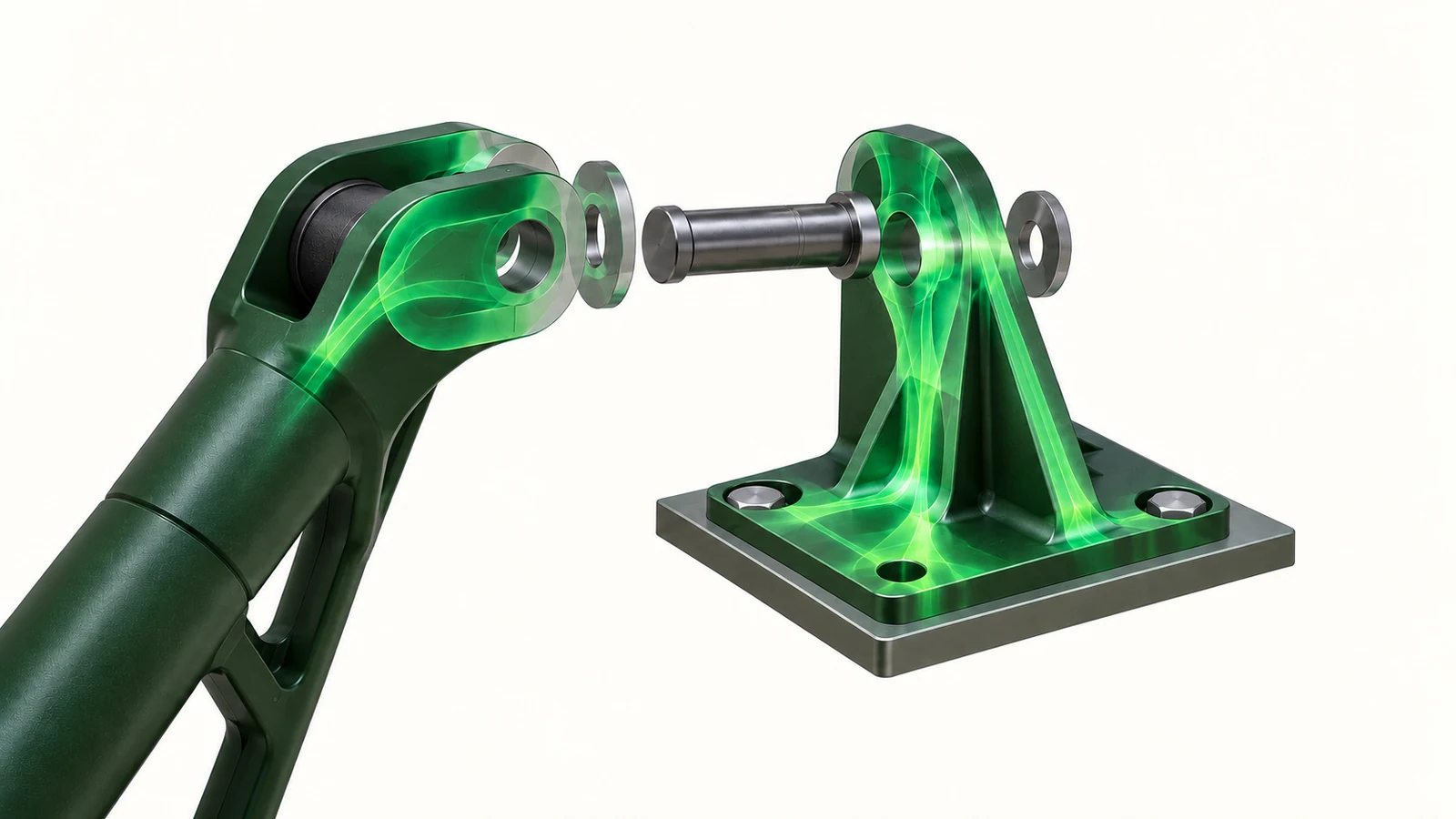
Sketch the connection as a sequence: ground contact, landing leg, bracket, fasteners, and airframe hard points. The bracket may see bending, bearing around holes, local clamp loads, or a combination, but the actual load case depends on vehicle mass, geometry, landing conditions, and the wider structure. Those inputs are not interchangeable with a generic “drone landing” assumption.
The useful design question is where the load enters and leaves the part. A change in section can create a local stress concentration; a fastener close to an edge can leave limited bearing area; a slot may ease adjustment but change the way load is transferred. These observations identify where the responsible designer should review the geometry. They do not replace structural analysis or set a universal minimum thickness.
| Bracket feature | Assembly function | Manufacturing/inspection focus |
|---|---|---|
| Airframe mounting face | Seats the bracket against the frame | Flatness and hole relationship to the leg interface. |
| Leg or skid seat | Sets the landing member’s position and angle | Contact geometry and orientation from the primary datum. |
| Fastener holes | Clamp and transfer load into the structure | Pattern position, edge condition, and specified clearance or thread. |
| Relief pockets | Reduce material away from load-bearing regions | Remaining wall support, cutter access, and distortion risk. |
The joint geometry controls assembly
Define which surfaces locate the bracket and which fasteners simply clamp it. If the leg is aligned by a machined seat, dimension that seat to the airframe datum. If the fastener pattern is intended to establish position, its relationship to the mounting face and leg axis becomes central. Without this hierarchy, a bracket may bolt on yet leave the leg skewed or unevenly loaded.
For a two-piece joint, show the mating part or provide its interface dimensions. A standalone bracket model may not reveal whether a counterbore needs tool access, whether a socket head clears the leg, or whether a clamp face is intended to contact across its full width. Include the assembly orientation and the direction of adjustment, if any.
Weight reduction has a boundary
Pocketing and sculpted transitions can reduce mass, but each cut changes section stiffness and machining support. Removing material near a fastener boss can reduce the available bearing region; deep pockets may leave thin walls that move under cutting forces or clamping. The lightest CAD model is not automatically the most repeatable part to manufacture or assemble.
Review the bracket together with adjacent structure. A heavier bracket may be counterproductive if it shifts the leg geometry or increases the load transmitted elsewhere; an aggressive relief may be equally unhelpful if it makes the feature fragile or difficult to inspect. Material and temper must be selected by the design authority for the operating environment and load case. If aluminum is under consideration, identify the exact alloy and condition and use a controlled material specification; the site’s обзор алюминия is background, not engineering approval.
Keep thin walls inspectable
Bracket geometry often mixes broad seating faces, perpendicular walls, holes, and pockets. Milling sequence should preserve stable support for the datum faces and avoid making a thin region the only clamping surface. Where a feature is likely to move as stock is removed, the manufacturing plan may need staged material removal, a change in support, or an inspection pause; the specific route depends on the part and the supplier’s process review.
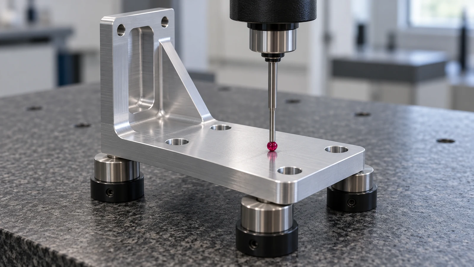
On the drawing, relate the leg seat and hole pattern to the same functional reference where appropriate. A list of hole diameters does not establish bracket alignment. Likewise, a flatness value without a defined inspection setup may be difficult to interpret on a flexible shape. Discuss how the part is supported and whether acceptance is based on free-state geometry or a defined assembly condition.
For complex access or multiple angled features, evaluate whether multi-axis milling helps reduce re-clamping. It is a process option, not a guarantee: the datum scheme, tool access, fixture design, and inspection plan still determine the result. See фрезерование с ЧПУ for the available process context.
Вопросы, которые нужно решить до выпуска
Before requesting a quote, align engineering, procurement, and manufacturing on a short set of inputs:
- What landing or ground-handling load cases govern the bracket, and who owns those assumptions?
- Which face, seat, or hole pattern locates the bracket to the airframe and leg?
- What fasteners, inserts, locking features, and tool clearances are required?
- Which dimensions control leg angle, symmetry, and contact with the mating structure?
- What material, temper, finish, corrosion protection, and edge treatment are approved?
- How should critical features be supported and inspected?
- Is the part a prototype, a design iteration, or a released production component?
Provide the drawing revision, 3D model, material specification, quantity, and any assembly context needed to interpret the interfaces. If analysis or qualification requirements are still open, identify them as open rather than asking the shop to fill the gap by choosing a convenient machining tolerance.
The most reliable bracket brief is specific about what must fit and who defines the loads. Once those boundaries are clear, CNC manufacturability can be assessed around tool access, workholding, feature relationships, and inspection—without confusing a machined part’s dimensional conformity with aircraft-level validation.