
The engineering objective is not to modernize symbols for appearance. It is to ensure that design, machining, and inspection use the same specification. A lone “Ra 0.8” may be familiar, yet still leave enough uncertainty for two instruments or suppliers to report different results.
Decode the callout in a fixed order
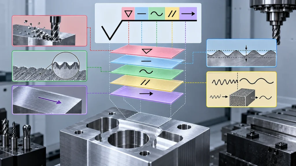 When a surface requirement arrives, do not jump directly to a machining operation. Read the callout from its governing standard outward:
This is a specific branch of the site’s broader Стандарты обработки на ЧПУ topic. It does not replace the drawing’s general tolerances, geometry controls, or finish/coating specification.
What changed from ISO 1302 to ISO 21920?
 ISO 1302 remains common on legacy drawings and in company templates, but ISO 21920 reorganized profile surface-texture specification, measurement, and parameter definitions into a newer series. ISO 21920-1 covers indication on technical product documentation; Parts 2 and 3 address terms, definitions, parameters, and specification operators.
The migration is not merely a new symbol shape. It asks drawing authors to define the specification with enough measurement context to obtain repeatable decisions. ISO’s official entry for ISO 21920-1:2021 states that it specifies rules for indicating surface texture by profile methods using graphical symbols.
ISO 1302 remains common on legacy drawings and in company templates, but ISO 21920 reorganized profile surface-texture specification, measurement, and parameter definitions into a newer series. ISO 21920-1 covers indication on technical product documentation; Parts 2 and 3 address terms, definitions, parameters, and specification operators.
The migration is not merely a new symbol shape. It asks drawing authors to define the specification with enough measurement context to obtain repeatable decisions. ISO’s official entry for ISO 21920-1:2021 states that it specifies rules for indicating surface texture by profile methods using graphical symbols.
| Legacy-drawing risk | Migration action |
|---|---|
| Title block names no surface-texture standard | State the governing standard and edition |
| Only an Ra number is shown | Review parameter, limit, filter, evaluation, and function |
| Old company symbol is copied without explanation | Translate its intended requirement, not its appearance |
| Supplier measures with default instrument settings | Agree settings and measurement direction before production |
Ra alone cannot describe how a surface will function
Ra is an arithmetic mean of profile deviations over the evaluated length. It compresses complex topography into one number. Two surfaces can share the same Ra yet differ in peak shape, valley depth, spacing, waviness, lay, scratches, and ability to retain lubricant or seal against a gasket.
Parameter selection should follow the failure mode. A sealing face may be sensitive to directional leakage paths and isolated valleys. A sliding surface may depend on peak behavior and lubricant retention. A cosmetic face may pass a roughness reading but fail because of tool witness marks or inconsistent brushing.
The article CNC surface roughness explores the relationship among Ra, function, machining, and cost. This page focuses on turning that engineering intent into a modern drawing indication.
Filtering and evaluation settings can change the result
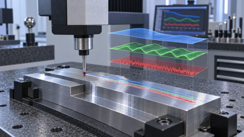 A stylus trace contains features at different spatial scales. Form, waviness, and roughness are separated through defined processing. If the designer and inspector use different filters, nesting indices, evaluation lengths, or end-treatment rules, their reported values can differ even on the same physical surface.
Before approving the drawing, answer these questions:
A stylus trace contains features at different spatial scales. Form, waviness, and roughness are separated through defined processing. If the designer and inspector use different filters, nesting indices, evaluation lengths, or end-treatment rules, their reported values can differ even on the same physical surface.
Before approving the drawing, answer these questions:
Small bores and narrow grooves may need replica methods, specialized probes, optical measurement, or a functional requirement instead of a conventional stylus trace. Specify something the supplier can verify on the actual geometry.
Lay direction belongs to the engineering decision
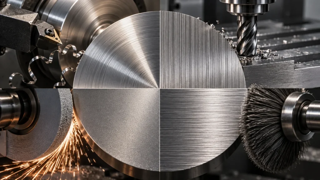 Toolpaths create direction. Turning commonly produces circumferential or helical marks; face milling creates arcs or cross patterns; grinding direction follows wheel motion; brushing deliberately creates a visual grain. That direction can affect sealing, friction, wear, optical appearance, and fluid movement.
If lay matters, state it with the appropriate symbol and identify the controlled zone. Do not assume “Ra 0.8” tells the machinist whether a sealing face may show a spiral path. If lay does not matter, avoid adding a requirement that forces a special operation without functional benefit.
Toolpaths create direction. Turning commonly produces circumferential or helical marks; face milling creates arcs or cross patterns; grinding direction follows wheel motion; brushing deliberately creates a visual grain. That direction can affect sealing, friction, wear, optical appearance, and fluid movement.
If lay matters, state it with the appropriate symbol and identify the controlled zone. Do not assume “Ra 0.8” tells the machinist whether a sealing face may show a spiral path. If lay does not matter, avoid adding a requirement that forces a special operation without functional benefit.
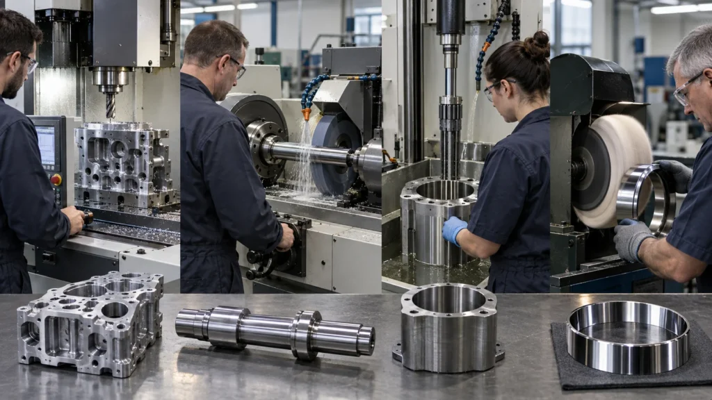
Secondary finishing can change both texture and dimensions. Use the варианты отделки поверхности overview to identify routes, then state whether the symbol applies before or after the chosen finish.
A drawing audit for surface-texture callouts
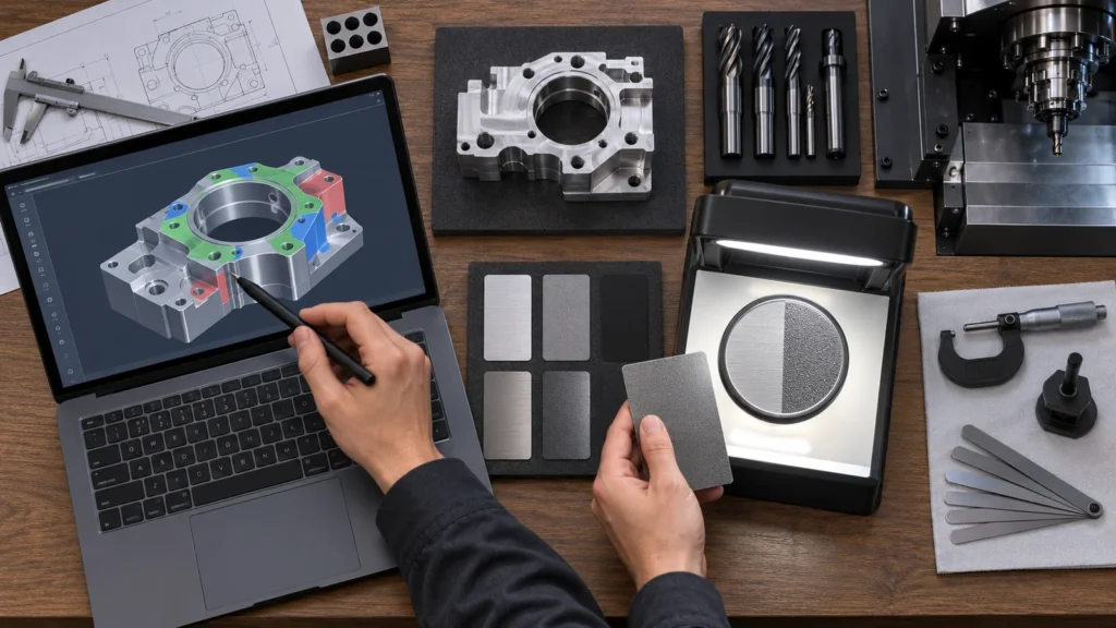 Before release, isolate every texture symbol and ask:
This audit often removes blanket roughness requirements from nonfunctional faces while strengthening the few surfaces that actually seal, slide, locate, or remain visible. That improves both manufacturability and inspection clarity.
ISO 21920 questions from CNC teams

Legacy drawings can remain contractually valid when they clearly state the edition and both parties understand the requirement. New or revised drawings should evaluate migration to ISO 21920 rather than silently mixing conventions.
Does a lower Ra always mean a better surface?
No. It can add cost without improving function, and it does not fully describe lay, waviness, defects, or functional peak-and-valley behavior.
Should roughness be measured before anodizing or plating?
The drawing or process specification should state the acceptance stage. A coating can alter the measured texture, fill valleys, reproduce substrate marks, or introduce its own variation.
Can a visual sample replace a texture measurement?
It can support cosmetic acceptance, but it does not automatically replace a specified profile measurement. Use both when appearance and functional texture are separate requirements.
A good surface symbol lets three people reach one decision: the designer knows what function is protected, the machinist knows which process condition to create, and the inspector knows how to evaluate it. ISO 21920 is most valuable when it closes that loop.