
The choice is therefore not “old manufacturing versus new manufacturing.” It is a decision about evidence. A prototype that looks correct can still give misleading test results when its material, surface, or directional strength differs from the intended product. Conversely, machining every early concept can consume budget before the geometry is stable. This guide compares the two processes by validation goal, part features, quantity, and inspection needs so engineers and buyers can choose a defensible route—or use both in sequence.
Define the Proof Before Choosing the Process
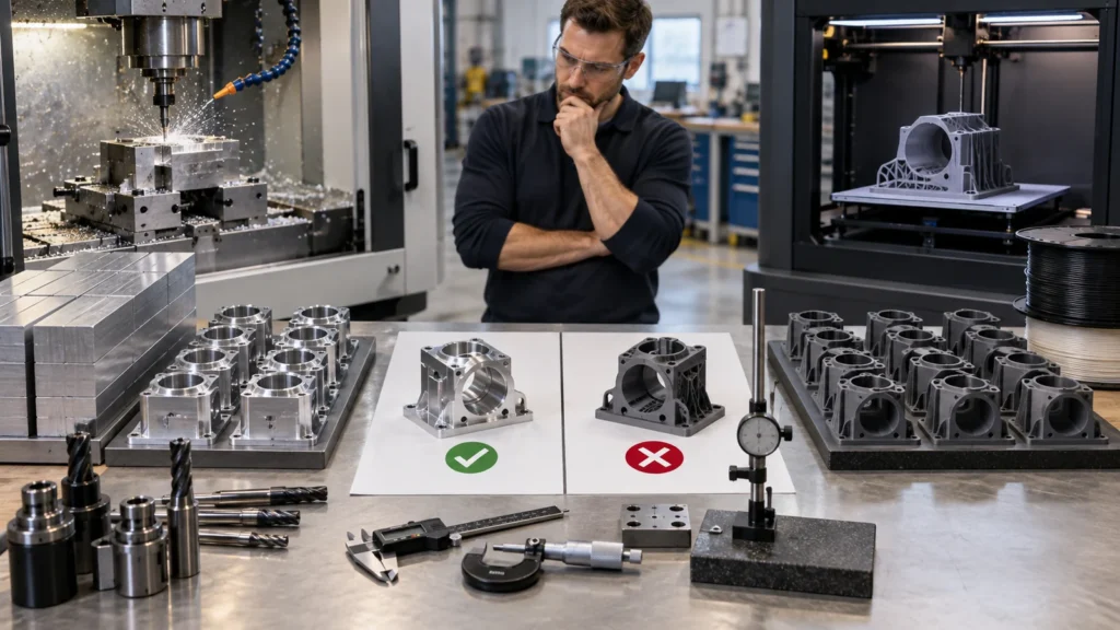 A prototype is not automatically successful because it matches the CAD model. It is successful only if it answers the engineering question that justified making it. A form model may need to confirm hand clearance and overall proportions. A functional prototype may need to carry load, seal fluid, transfer heat, survive fasteners, or locate other components. A pre-production part may need to demonstrate that the drawing, inspection plan, and manufacturing route can work repeatedly.
These purposes demand different levels of fidelity. For an enclosure shape review, exact production material may add little value. For a heat sink, pump manifold, instrument housing, or structural bracket, material conductivity, stiffness, flatness, and threaded features may be central to the test. The most efficient process is the least expensive route that preserves the variables the test depends on—not simply the route with the lowest piece price.
A prototype is not automatically successful because it matches the CAD model. It is successful only if it answers the engineering question that justified making it. A form model may need to confirm hand clearance and overall proportions. A functional prototype may need to carry load, seal fluid, transfer heat, survive fasteners, or locate other components. A pre-production part may need to demonstrate that the drawing, inspection plan, and manufacturing route can work repeatedly.
These purposes demand different levels of fidelity. For an enclosure shape review, exact production material may add little value. For a heat sink, pump manifold, instrument housing, or structural bracket, material conductivity, stiffness, flatness, and threaded features may be central to the test. The most efficient process is the least expensive route that preserves the variables the test depends on—not simply the route with the lowest piece price.
Two Routes Create Different Material Histories
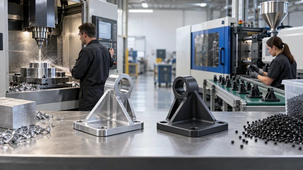
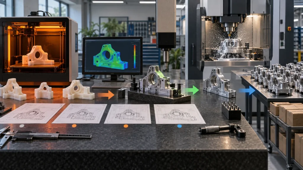 CNC machining is subtractive. A mill or lathe removes material from solid stock until the required geometry remains. The starting stock already has a manufacturing history—such as extrusion, rolling, casting, or molding—and its condition influences strength, stability, and machinability. This route is valuable when the test depends on a known grade, temper, or commercially available engineering plastic.
3D printing is additive. It creates geometry layer by layer by depositing, curing, sintering, or melting material. “3D printed” is not one material condition: FDM thermoplastics, photopolymer resins, powder-bed polymers, and printed metals behave differently. Build orientation, support strategy, thermal history, porosity, post-curing, and heat treatment can all influence performance. A printed material with a familiar trade name should not be assumed to behave exactly like machined stock of a similarly named polymer or alloy.
This distinction is often more important than nominal material strength on a datasheet. If the planned test involves fatigue, impact, heat, chemical exposure, long-term creep, or load across layer boundaries, the team should confirm whether the printed material and build condition represent the intended product. When production-grade stock matters, the broader Материалы для ЧПУ-обработки decision should be resolved before comparing prices.
CNC machining is subtractive. A mill or lathe removes material from solid stock until the required geometry remains. The starting stock already has a manufacturing history—such as extrusion, rolling, casting, or molding—and its condition influences strength, stability, and machinability. This route is valuable when the test depends on a known grade, temper, or commercially available engineering plastic.
3D printing is additive. It creates geometry layer by layer by depositing, curing, sintering, or melting material. “3D printed” is not one material condition: FDM thermoplastics, photopolymer resins, powder-bed polymers, and printed metals behave differently. Build orientation, support strategy, thermal history, porosity, post-curing, and heat treatment can all influence performance. A printed material with a familiar trade name should not be assumed to behave exactly like machined stock of a similarly named polymer or alloy.
This distinction is often more important than nominal material strength on a datasheet. If the planned test involves fatigue, impact, heat, chemical exposure, long-term creep, or load across layer boundaries, the team should confirm whether the printed material and build condition represent the intended product. When production-grade stock matters, the broader Материалы для ЧПУ-обработки decision should be resolved before comparing prices.
A Buyer’s Decision Matrix—Without Universal Winners
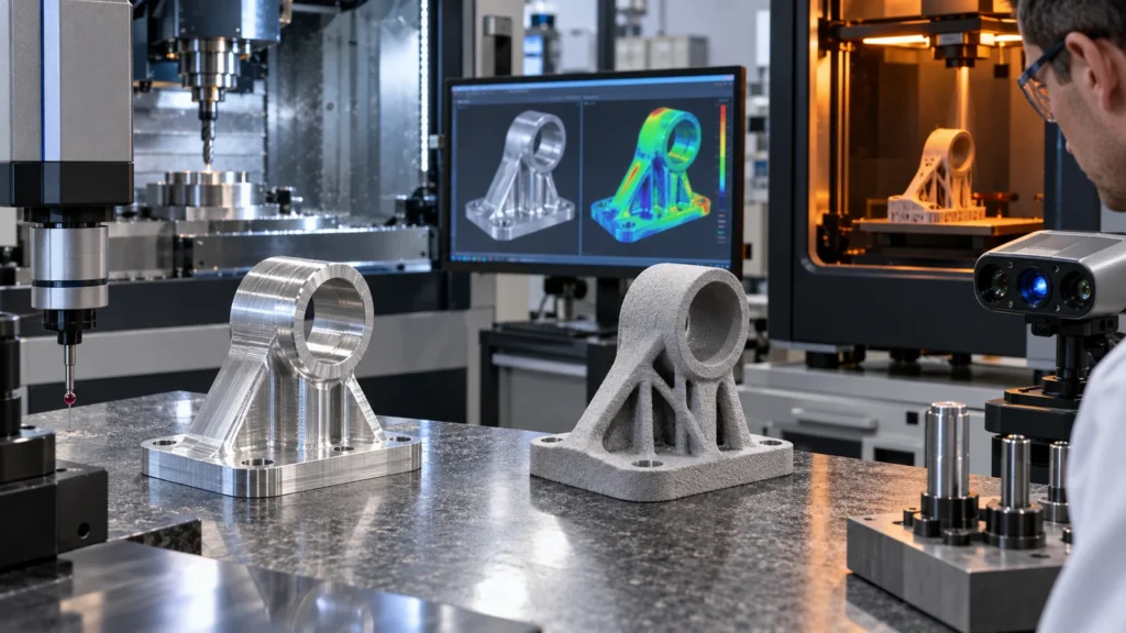 Most comparison charts declare one process “better” in each row. Real projects are less tidy. Printer type, machine access, stock form, part size, geometry, material, and supplier capability can overturn a generic rule. Use the matrix below as a screening tool, then ask suppliers to quote the actual model and drawing.
The matrix deliberately avoids fixed tolerance and quantity thresholds. A small milled aluminum plate and a large deep-pocketed housing do not share the same economics. Likewise, a desktop filament print and an industrial metal powder-bed part should not be treated as one process. Any quoted threshold without a material, machine, geometry, feature size, and inspection condition is only a rough marketing shortcut.
Geometry Can Reverse the Obvious Answer
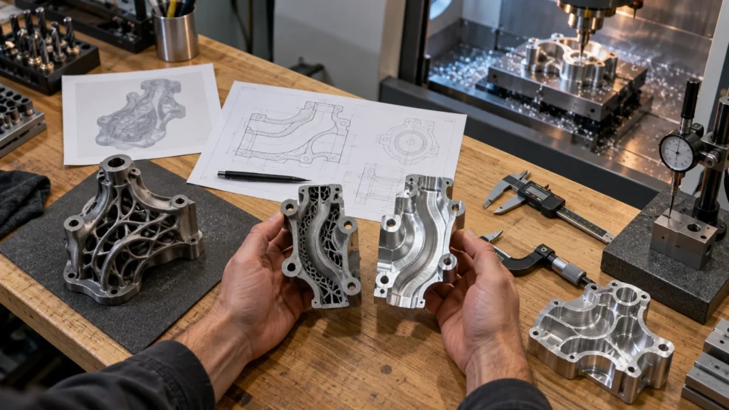 Part shape affects both feasibility and cost. CNC tools need physical access. Deep narrow pockets may require long tools that are less rigid. Small internal corner radii can demand smaller cutters and slower toolpaths. Multiple inaccessible faces may require more setups, dedicated fixtures, or multi-axis machining. If an internal channel cannot be reached from an opening, ordinary machining cannot create it as a single closed feature.
Additive processes remove many tool-access constraints, but they introduce their own design rules. Overhangs may need supports; supports must be removed from reachable areas; trapped powder may need escape paths; thin walls can distort; broad flat areas can move during building or cooling; and some surfaces may be inaccessible for post-processing. A “printable” CAD model is not necessarily a cleanable, inspectable, or production-ready component.
The decision can also change at feature level. A housing may be straightforward to print as one body, yet its bearing bores and gasket face may still need machining. Another part may be easy to machine except for a conformal cooling passage, making a printed near-net body with finish-machined interfaces more rational. This feature-by-feature view is more useful than forcing an entire assembly into one technology.
Part shape affects both feasibility and cost. CNC tools need physical access. Deep narrow pockets may require long tools that are less rigid. Small internal corner radii can demand smaller cutters and slower toolpaths. Multiple inaccessible faces may require more setups, dedicated fixtures, or multi-axis machining. If an internal channel cannot be reached from an opening, ordinary machining cannot create it as a single closed feature.
Additive processes remove many tool-access constraints, but they introduce their own design rules. Overhangs may need supports; supports must be removed from reachable areas; trapped powder may need escape paths; thin walls can distort; broad flat areas can move during building or cooling; and some surfaces may be inaccessible for post-processing. A “printable” CAD model is not necessarily a cleanable, inspectable, or production-ready component.
The decision can also change at feature level. A housing may be straightforward to print as one body, yet its bearing bores and gasket face may still need machining. Another part may be easy to machine except for a conformal cooling passage, making a printed near-net body with finish-machined interfaces more rational. This feature-by-feature view is more useful than forcing an entire assembly into one technology.
Tolerance, Surface, and Inspection Are One Decision
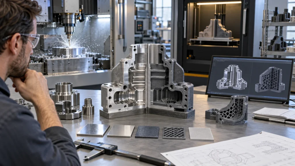 Tolerance is not a single number attached to a process. It belongs to a feature and its function. A critical bore may control alignment; a flat face may control sealing; a hole pattern may control assembly; and a cosmetic outer profile may tolerate much more variation. The chosen datum system, part orientation, material movement, setup sequence, and measurement method all influence whether those requirements can be demonstrated.
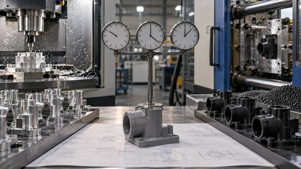
CNC machining commonly offers an efficient path to controlled bores, planar faces, threads, and accessible datum features. However, tighter requirements can add finishing passes, tool control, extra setups, temperature management, and inspection time. Printed parts can also be accurate enough for many uses, but their dimensional behavior varies by technology, material, orientation, geometry, and post-processing. Critical printed features may need machining rather than relying on the as-built result.
Surface condition belongs in the same discussion. Visible layer texture may be harmless on a form model but unacceptable on a seal, sliding interface, optical seat, or appearance surface. An as-machined finish may satisfy function yet still need blasting, anodizing, polishing, passivation, or another treatment. Teams should specify functional zones rather than demand one premium finish everywhere; the same principle applies to both the Допуски при ЧПУ-обработке plan and the surface-finish plan.
Tolerance is not a single number attached to a process. It belongs to a feature and its function. A critical bore may control alignment; a flat face may control sealing; a hole pattern may control assembly; and a cosmetic outer profile may tolerate much more variation. The chosen datum system, part orientation, material movement, setup sequence, and measurement method all influence whether those requirements can be demonstrated.
CNC machining commonly offers an efficient path to controlled bores, planar faces, threads, and accessible datum features. However, tighter requirements can add finishing passes, tool control, extra setups, temperature management, and inspection time. Printed parts can also be accurate enough for many uses, but their dimensional behavior varies by technology, material, orientation, geometry, and post-processing. Critical printed features may need machining rather than relying on the as-built result.
Surface condition belongs in the same discussion. Visible layer texture may be harmless on a form model but unacceptable on a seal, sliding interface, optical seat, or appearance surface. An as-machined finish may satisfy function yet still need blasting, anodizing, polishing, passivation, or another treatment. Teams should specify functional zones rather than demand one premium finish everywhere; the same principle applies to both the Допуски при ЧПУ-обработке plan and the surface-finish plan.
Finally, ask what evidence will accompany the part. A visual model may need only a basic check. A functional sample may need a dimensional report for selected characteristics. A release candidate may need material documentation, defined inspection methods, revision control, and repeatable records. If evidence is part of the deliverable, state it at quotation rather than after the parts arrive.
Quantity Changes the Economics—but Not in One Direction
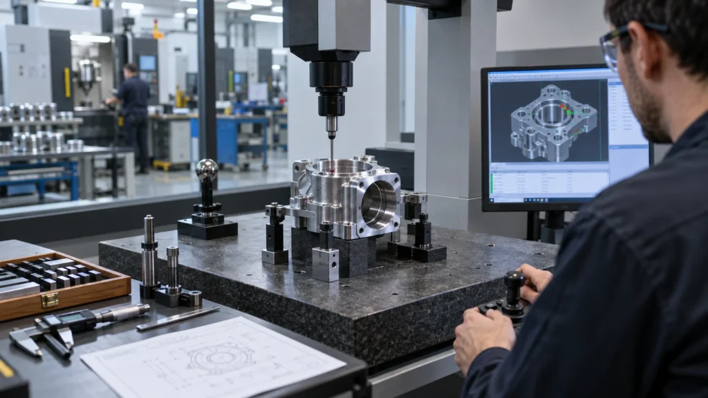 3D printing often has a low barrier for the first part because it needs no cutting program or conventional fixture. That advantage is strongest when the design is changing, the quantity is very small, and the build can use an existing machine/material combination. Yet print cost is not independent of volume: build time, orientation, support consumption, packing efficiency, finishing labor, inspection, and failure risk remain part of every unit.
CNC machining carries upfront process work. CAM programming, tool selection, setup planning, workholding, probing, and first-piece verification must happen before a stable cycle exists. Once that work is established, additional parts may use the same program and fixture, spreading nonrecurring effort over the batch. But this does not mean machining always wins above a universal quantity. A simple plate and a five-sided housing have different setup burdens; a small printed part and a large metal build have different capacity costs.
Request comparable quotations rather than applying an internet crossover number. The supplier should quote the same revision, material intent, finish, inspection level, delivery basis, and quantity breaks. Also consider the cost of a wrong answer. A cheaper prototype that cannot represent the load path or mating interface may create a false pass or false failure—both can cost more than the part itself.
3D printing often has a low barrier for the first part because it needs no cutting program or conventional fixture. That advantage is strongest when the design is changing, the quantity is very small, and the build can use an existing machine/material combination. Yet print cost is not independent of volume: build time, orientation, support consumption, packing efficiency, finishing labor, inspection, and failure risk remain part of every unit.
CNC machining carries upfront process work. CAM programming, tool selection, setup planning, workholding, probing, and first-piece verification must happen before a stable cycle exists. Once that work is established, additional parts may use the same program and fixture, spreading nonrecurring effort over the batch. But this does not mean machining always wins above a universal quantity. A simple plate and a five-sided housing have different setup burdens; a small printed part and a large metal build have different capacity costs.
Request comparable quotations rather than applying an internet crossover number. The supplier should quote the same revision, material intent, finish, inspection level, delivery basis, and quantity breaks. Also consider the cost of a wrong answer. A cheaper prototype that cannot represent the load path or mating interface may create a false pass or false failure—both can cost more than the part itself.
The Strongest Workflow May Use Both
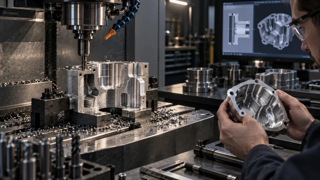 A disciplined development program can change process as uncertainty decreases. Early printed models can expose access problems, assembly collisions, cable routing issues, and ergonomic mistakes while CAD is still moving. Once the architecture is stable, machined prototypes can test production material, interfaces, thermal behavior, fasteners, and repeatability. The sequence prevents expensive precision from being applied to an immature design.
Both processes may also appear in one build. Printed soft jaws, drill guides, inspection nests, handling tools, or assembly fixtures can support machined parts. Printed bodies can receive machined datums, bores, threads, sealing faces, or mounting surfaces. A complex assembly can use printed non-load-bearing ducts and machined structural interfaces. These are not compromises; they assign each requirement to the process best equipped to control it.
The transition should be intentional. Record which prototype features were representative and which were placeholders. When moving toward a CNC prototype-to-production route, freeze critical interfaces, release a controlled drawing, confirm material and finish, and identify the inspection records needed for approval. Otherwise, the team may learn the wrong lesson from a prototype that was never designed to reproduce production behavior.
A disciplined development program can change process as uncertainty decreases. Early printed models can expose access problems, assembly collisions, cable routing issues, and ergonomic mistakes while CAD is still moving. Once the architecture is stable, machined prototypes can test production material, interfaces, thermal behavior, fasteners, and repeatability. The sequence prevents expensive precision from being applied to an immature design.
Both processes may also appear in one build. Printed soft jaws, drill guides, inspection nests, handling tools, or assembly fixtures can support machined parts. Printed bodies can receive machined datums, bores, threads, sealing faces, or mounting surfaces. A complex assembly can use printed non-load-bearing ducts and machined structural interfaces. These are not compromises; they assign each requirement to the process best equipped to control it.
The transition should be intentional. Record which prototype features were representative and which were placeholders. When moving toward a CNC prototype-to-production route, freeze critical interfaces, release a controlled drawing, confirm material and finish, and identify the inspection records needed for approval. Otherwise, the team may learn the wrong lesson from a prototype that was never designed to reproduce production behavior.
Four Project Scenarios Show Where the Choice Moves
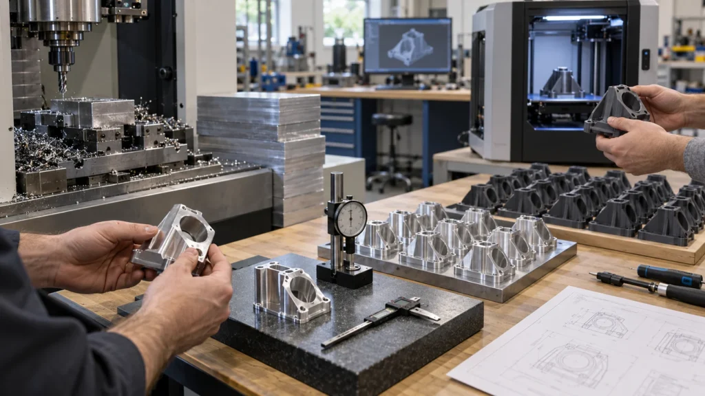
The immediate risks are grip, button access, cable exits, and packaging volume. A printed model allows rapid revisions and can reveal assembly interference before detailed machining work is justified. Inserts or representative hardware can be added when thread behavior is not yet the main test.
2. Aluminum thermal housing for bench testing
Heat transfer, flat contact areas, threaded fasteners, and component location are central. A machined part in the intended aluminum grade gives more relevant evidence than a polymer shape model. The drawing should identify contact faces, flatness needs, thread class, and which dimensions require reporting.
3. Fluid manifold with curved internal passages
Additive manufacturing may create the passage network without drilling intersections and plugs. However, ports, mounting datums, valve seats, and sealing faces can still require finish machining and inspection. The process plan must also consider support or powder removal, internal cleanliness, leak testing, and whether hidden channels can be verified.
4. Ten functional brackets followed by repeat orders
If the bracket uses standard plate or billet, carries meaningful load, and has accessible geometry, machining may support both validation and later repeat batches. A printed form check can still precede it if mounting access is uncertain. The economic comparison should include reusable workholding, repeat inspection, and revision stability—not only the first-unit price.
Build a Process-Neutral Quote Package
 Buyers obtain better recommendations when the request describes function instead of naming a process too early. Provide a 3D model and a controlled drawing, then separate fixed requirements from preferences. A supplier can only suggest alternatives safely when it knows which characteristics cannot move.
This information lets a manufacturer compare routes without quietly relaxing function. It also exposes when a mixed route is appropriate. The broader CNC machining advantages and disadvantages are best judged against a specific part and validation plan, not as universal claims about the technology.
Buyer FAQs
No. Strength depends on the material, stock or build condition, geometry, loading direction, defects, heat treatment, and environment. CNC machining is often preferred when a test must use a known wrought grade or production-equivalent plastic, while a qualified additive process may be superior for a geometry designed specifically for printing. Compare the actual material condition and load case rather than the process name.
Is 3D printing always cheaper for one part?
No. It frequently reduces preparation for a one-off model, but a large build, costly material, extensive supports, long post-processing, or required finish machining can change the result. A simple part cut from available stock may be economical to machine even at quantity one. Quote the same requirements through both routes when the decision is close.
Can a printed prototype validate a machined production part?
It can validate geometry, packaging, handling, and some assembly questions. It may not validate the production part’s stiffness, thermal behavior, wear, fatigue, sealing, surface interaction, or thread performance. The test plan should explicitly state which findings can transfer and which require a production-material sample.
When should critical features be machined after printing?
Consider finish machining when datums, bearing seats, threaded connections, sealing lands, precision bores, flat mounting faces, or other interfaces exceed the dependable as-built capability. The printed design must include machining allowance, accessible reference features, and a practical workholding strategy.
Should the drawing specify CNC machining or 3D printing?
Specify a process when function, regulation, qualification, material history, or a validated production route makes it necessary. Otherwise, define the material, geometry, critical characteristics, surface requirements, inspection evidence, and prohibited changes. That gives qualified suppliers room to recommend a better route without weakening the design intent.