
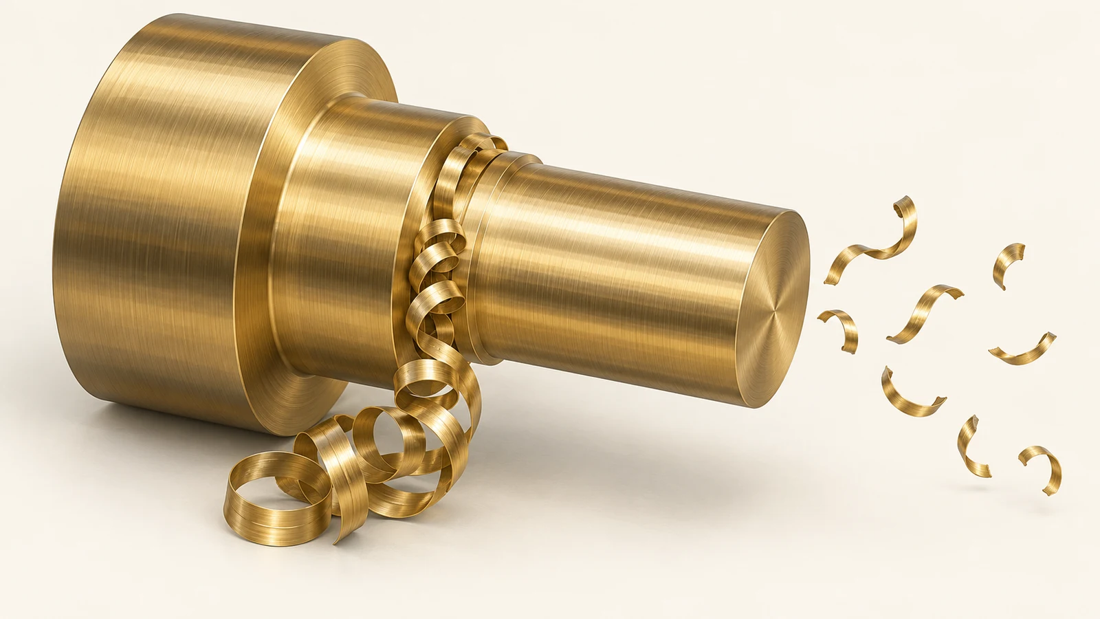
When brass chips wrap around a tool, brush across a finished surface, or bridge a narrow slot, the first response is often to blame the alloy. That may be part of the story, but chip control is also a cutting-system problem: feature geometry, engagement, edge condition, coolant delivery, evacuation path, and operation sequence decide whether the chip breaks, clears, or returns to the cut.
The useful question is not simply “Which brass makes short chips?” It is: where does the chip become trapped, what form does it take at that point, and can the process create a safe route out of the feature? This troubleshooting guide follows that sequence so a buyer or process engineer can separate an alloy-selection issue from a toolpath or access problem.
Map the chip before changing the alloy
Record the operation, tool, feature, and chip destination. A long continuous ribbon from a turned diameter behaves differently from compact fragments produced while milling a pocket. Note whether the chip loops around the workpiece, nests in a cross-hole, scratches a finished face, or blocks coolant. Take a photograph only after the machine is in a safe state; never reach into a machine enclosure to retrieve a chip while equipment is running.
Next, compare the chip with the part. If a chip is harmlessly carried out of an open turning cut, its length may not matter. If the same ribbon can wind around a small shaft or be dragged across a sealing surface, the geometry of the part makes it consequential. For a deep pocket, the main constraint may be evacuation rather than chip length: even a short fragment can remain in a blind corner where the next pass recuts it.
Separate three observations in the process record: chip shape, chip location, and resulting defect. “Long chips” is incomplete. “Continuous ribbon accumulates behind the shoulder and scratches the finished journal during the next pass” points to a testable mechanism.
What turns a manageable chip into a wrap
A chip wraps when it stays attached long enough to follow the rotating work or cutter, and when there is no clear path for it to leave. On turning work, a continuous ribbon can wind around the part or tool. In milling, chips can be recut because they remain in a pocket or are pulled back through the cutting zone. Small holes, narrow slots, and shoulders create local traps even when the overall part is open.
Tool edge condition changes the chip. A worn or unsuitable edge may rub, smear, or form a chip that is difficult to break. Engagement also matters: the amount of material removed per tooth or per revolution influences chip thickness and shape. There is no universally correct feed or speed value without the exact alloy, tooling, geometry, machine, and setup. Use the tooling supplier’s guidance and a controlled trial rather than copying a number from a different brass grade or machine.
Coolant can help carry chips away when its direction and pressure reach the cutting zone, but coolant cannot compensate for a closed-off geometry or a toolpath that packs chips into a corner. In some features, a tool change or a revised sequence is more effective than increasing coolant flow. If the part needs torneamento CNC, evaluate chip flow around shoulders, grooves, and bores as part of the turning strategy.
Read the feature pattern
| Where chips collect | What to investigate | Why the location matters |
|---|---|---|
| Behind a turned shoulder | Chip direction, tool approach, and relief at the shoulder | The shoulder can stop a ribbon from traveling away from the part |
| Inside a pocket or slot | Evacuation clearance, cutter engagement, and pass order | Recut fragments can damage the floor or side wall |
| At a cross-hole intersection | Drilling sequence and chip access from each opening | The second operation may trap or fold chips from the first |
| On a finished diameter | Whether chips return to the surface during a later pass | A chip can scratch an otherwise acceptable finish |
| Near a tool or holder | Clearance, guarding, and chip evacuation path | A wrap can become a process-safety issue, not just a cosmetic defect |
The pattern can also show whether the issue is stable. If chips collect in the same pocket corner on every part, the path may be predictable and correctable. If the location varies with tool wear or batch position, check the cutting edge and process controls before redesigning the part. If the problem appears only after a particular secondary feature, review the order of operations.
For intersecting passages, inspect both the entrance and exit after each operation. A chip may look cleared from one side while remaining lodged deeper in the passage. Do not rely on a final air blast as the only evidence that a complex cavity is clean; define the required cleanliness level and an inspection method suited to the feature.
Adjust cutting and operation order
Start with a low-risk sequence of checks. Confirm that the correct tool and insert are installed, inspect the edge for wear or damage, and verify that the chip path is not blocked by a fixture or adjacent geometry. Then change one process variable at a time. Depending on the operation, a different tool geometry, engagement, pass direction, or chip-breaking strategy may be worth testing. Keep the workholding and inspection method consistent so the outcome is attributable.
Operation order can matter more than expected. If a cross-hole is drilled before a nearby pocket is opened, the later operation may create an exit that helps chips clear—or it may push material into the hole. Conversely, drilling after the surrounding surfaces are finished may leave chips on a surface that is difficult to clean without damage. Compare sequence options using a sample and inspect the actual chip path, not just the program simulation.
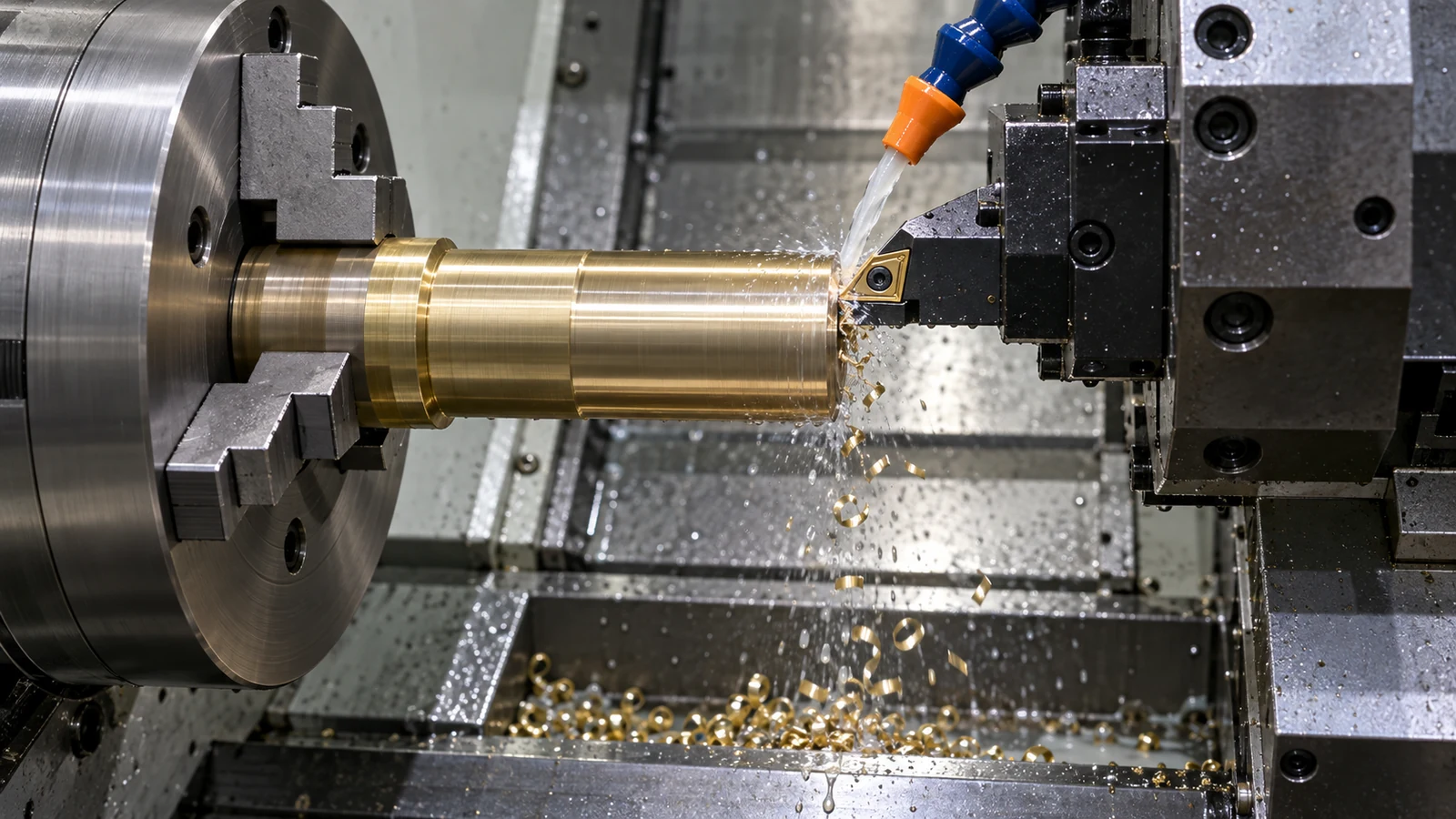
For production, a chip-control adjustment must also be checked for tool life, cycle stability, and downstream finishing. A process that produces shorter chips but increases edge wear or changes a critical surface is not an improvement. Record the starting condition, adjustment, number of parts evaluated, and the effect on both chips and part features.
When alloy selection really matters
Alloy choice matters when the part’s functional requirements leave room for alternatives and when material behavior is consistently limiting the process. Different brass grades can vary in machinability, forming behavior, corrosion requirements, conductivity, and restrictions on lead content. The correct choice depends on the part and its service conditions; “best chip control” cannot be considered in isolation from those constraints.
Before changing grade, confirm the required specification, temper, regulatory or customer restrictions, and any joining or finishing needs. Compare the exact material designations—not just broad labels such as “free-machining brass.” The site’s brass material information is a starting point for understanding the available material family, while the drawing and purchase specification control the actual requirement.
If the alloy is fixed, process engineering should focus on tooling, access, engagement, evacuation, and sequence. If the alloy is open to review, treat a grade change as a design decision: verify the impact on strength, corrosion exposure, conductivity, forming, and downstream operations. A chip-control issue is not enough evidence by itself to approve a material substitution.
Questions buyers and engineers ask
Are long brass chips always a sign of a bad cutting condition?
Not always. A continuous chip can be manageable when it clears safely and does not contact the part or tool. It becomes a problem when it wraps, nests in a feature, blocks flow, or damages a surface.
Should a shop change brass grade to solve chip wrapping?
Only after the part requirements allow a substitution and the process evidence points to material behavior as a primary constraint. First rule out worn tooling, poor access, trapped chips, and an operation sequence that prevents evacuation.
Can coolant alone prevent chips from recutting?
It may help in an accessible cutting zone, but it cannot guarantee evacuation from a blind pocket or blocked passage. Review geometry, toolpath, and chip exit routes as well as coolant direction.