
Introduzione: L'ascesa della precisione robotica nella produzione
Per decenni, il reparto produttivo è stato dominato dal mondo rigido, potente e preciso delle macchine CNC (Controllo Numerico Computerizzato). Queste macchine instancabili hanno definito la produzione di massa, offrendo una precisione senza pari per le produzioni ad alto volume. Tuttavia, una rivoluzione silenziosa è andata crescendo, spinta dalla necessità di una maggiore agilità e dalla capacità di gestire pezzi più grandi e complessi. Questa rivoluzione è alimentata dalla robotica, che si è evoluta da semplici manipolatori di materiale a sofisticati centri di lavorazione. La convergenza di tecnologie avanzate di sensoristica, potenti software di programmazione offline e bracci robotici ad alta precisione ha dato origine a un nuovo paradigma: lavorazione robotica dei giunti. Questo approccio non consiste nel sostituire completamente le CNC, ma nell'ampliare i confini di ciò che è possibile, portando la precisione automatizzata a compiti e pezzi che un tempo erano considerati poco pratici o proibitivamente costosi da automatizzare. L'ascesa della precisione robotica segna un passaggio verso celle di produzione flessibili e riconfigurabili, in grado di adattarsi ai cambiamenti di prodotto con tempi di inattività minimi, modificando radicalmente l'economia e le capacità della produzione moderna.
Che cos'è la lavorazione robotica dei giunti? Definizione della tecnologia principale
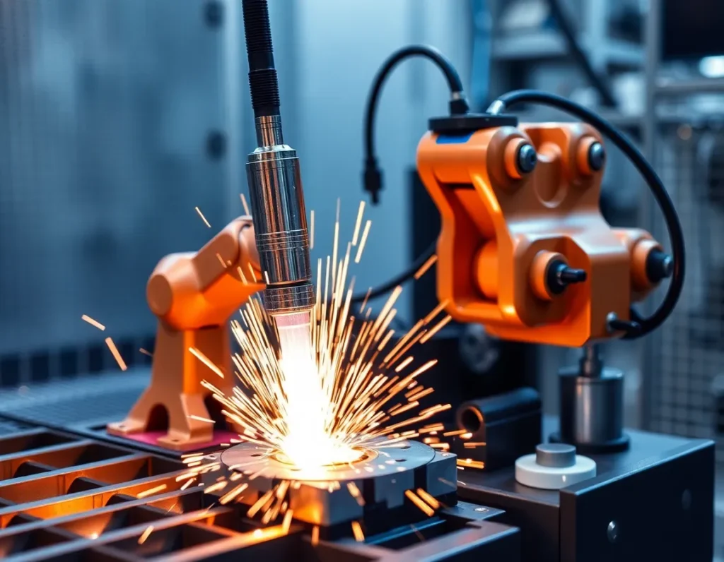
Alla base, la lavorazione robotica dei giunti è un processo di produzione per sottrazione in cui un braccio robotico industriale multiasse, dotato di un mandrino rotante e di un utensile da taglio, esegue operazioni di lavorazione come fresatura, foratura, scanalatura, sbavatura o lucidatura. Il termine “giunto” si riferisce ai giunti articolati e rotanti del braccio robotico—tipicamente sei o più—che ne consentono l'ampia gamma di movimento e la destrezza. A differenza di una macchina CNC, in cui l'utensile da taglio si muove lungo guide lineari (assi X, Y, Z), un sistema di lavorazione robotico muove l'utensile attraverso la complessa coordinazione dei suoi giunti rotanti. È questa struttura cinematica a conferire al robot la sua eccezionale flessibilità, permettendogli di manovrare gli utensili ad angoli non convenzionali e di accedere a spazi ristretti su geometrie grandi e complesse come stampi, strutture aerospaziali o componenti architettonici.
La tecnologia trascende la semplice automazione. Un vero sistema di lavorazione robotica dei giunti integra diversi elementi critici: il robot stesso, un mandrino ad alta frequenza in grado di raggiungere gli RPM necessari per il taglio, un sensore di forza-coppia per il controllo adattivo e un software sofisticato che traduce un modello CAD in un percorso utensile impeccabile e privo di collisioni che il robot può seguire. È questa integrazione di meccanica, sensoristica e intelligenza a definire la moderna lavorazione robotica, consentendole di affrontare materiali che vanno dalle schiume morbide e dai compositi ai metalli come l'alluminio e persino l'acciaio con competenza crescente.
Componenti e sistemi chiave di una cella di lavorazione robotica
Una cella di lavorazione robotica è un sistema sinergico in cui ogni componente svolge un ruolo vitale nel raggiungimento della precisione e delle prestazioni richieste. Comprendere queste parti è essenziale per cogliere le capacità della tecnologia.
Il manipolatore robotico
Questo è il braccio articolato, l'elemento fisico di “lavorazione dei giunti”. Le specifiche chiave includono la capacità di carico utile (per trasportare il mandrino e resistere alle forze di taglio), la portata, la ripetibilità (spesso nell'intervallo da ±0,05 mm a ±0,1 mm per i modelli da lavorazione) e la rigidità. I robot per impieghi gravosi con strutture rinforzate vengono generalmente scelti per ridurre al minimo la deflessione durante il taglio.
Mandrino e utensileria
Il mandrino è il cuore dell'azione di taglio. I mandrini per la lavorazione robotica sono tipicamente unità ad alta frequenza (spesso 20.000 RPM e oltre), azionate elettricamente, che forniscono la velocità e la potenza per l'asportazione del materiale. Sono montati sulla flangia dell'utensile a fine braccio (EOAT) del robot. I cambi utensili automatici (ATC) sono spesso integrati per consentire a un singolo robot di eseguire più operazioni—foratura, poi fresatura, poi sbavatura—senza intervento manuale.
Sistema di controllo e software
Questo è il cervello dell'operazione. È costituito dal controller del robot e, cosa cruciale, da software avanzato di programmazione offline (OLP) e simulazione. Il software OLP consente ai programmatori di creare, ottimizzare e simulare l'intero processo di lavorazione in un ambiente 3D virtuale. Genera il codice complesso che coordina tutti i giunti del robot per muovere l'utensile lungo il percorso preciso, simulando al contempo i tempi di ciclo e verificando le collisioni con il pezzo, le attrezzature o il robot stesso.
Sistemi di rilevamento e feedback
Per compensare la rigidità intrinsecamente inferiore di un robot a catena cinematica seriale rispetto a una macchina CNC, le celle avanzate impiegano sistemi di feedback in tempo reale. Un sensore di forza-coppia montato tra il polso del robot e il mandrino misura le forze di taglio. Questi dati vengono inviati a un sistema di controllo adattivo che può regolare dinamicamente la velocità di avanzamento o il percorso del robot per mantenere condizioni di taglio ottimali, prevenendo la rottura dell'utensile e garantendo una qualità costante, soprattutto su pezzi con variazioni sconosciute.
Sistemi di fissaggio del pezzo e assi esterni
Il pezzo deve essere fissato saldamente, spesso utilizzando attrezzature modulari. Per la lavorazione di pezzi molto grandi o per ottenere orientamenti specifici, il pezzo può essere montato su un posizionatore motorizzato o una tavola rotante (un asse esterno). Ciò aumenta efficacemente i gradi di libertà del sistema, consentendo al robot di accedere a tutti i lati di un pezzo senza riattrezzaggio, migliorando notevolmente l'efficienza per componenti complessi.
I vantaggi della lavorazione robotica a giunti: precisione, flessibilità e costo
L'adozione della lavorazione robotica a giunti è guidata da una serie convincente di vantaggi che affrontano le sfide chiave della produzione moderna.
Flessibilità e inviluppo di lavoro senza pari: Questo è il vantaggio principale. Un robot standard a 6 assi può manipolare un utensile attorno a un pezzo in modi che una macchina CNC a 3 o persino 5 assi non può, raggiungendo cavità profonde o lavorando con angoli composti severi. L'inviluppo di lavoro—lo spazio fisico a cui il robot può accedere—è anche significativamente più ampio per ingombro e costo rispetto a una macchina CNC. Ciò rende i robot ideali per pezzi molto grandi come pale di turbine eoliche, scafi di imbarcazioni o sezioni di aeromobili che richiederebbero un colossale portale CNC costruito su misura.
Convenienza per pezzi grandi e volumi da bassi a medi: L'investimento di capitale per una cella robotica è spesso inferiore a quello per una macchina CNC di dimensioni equivalenti. Per la lavorazione di pezzi grandi, il risparmio sui costi è notevole. Inoltre, i robot eccellono nella produzione a volumi da bassi a medi e ad alta varietà. Una singola cella robotica può essere rapidamente riprogrammata e riattrezzata per eseguire operazioni diverse su pezzi diversi, massimizzando l'utilizzo degli asset e consentendo una produzione economica in piccoli lotti.
Integrazione senza soluzione di continuità nelle linee automatizzate: Un robot è intrinsecamente progettato per l'automazione. Una cella di lavorazione robotica può essere facilmente integrata con altri robot per il carico/scarico dei pezzi, con sistemi di visione per la localizzazione dei pezzi o con trasportatori per creare una linea di produzione completamente automatizzata. Ciò crea un flusso continuo dalla materia prima al pezzo finito con una movimentazione umana minima.
Riduzione del tempo non di taglio e finitura complessa: Robots can perform multiple processes in a single setup. After milling, the same robot can automatically switch to a sanding pad or polishing wheel to finish the surface, eliminating the time and potential inaccuracies of moving the part to a separate station. Their dexterity also makes them perfect for tedious, labor-intensive tasks like deburring or creating consistent cosmetic finishes on complex contours.
Common Applications and Industries Transformed by Robotic Machining
The unique strengths of robotic joint machining have made it a transformative technology across several key industries.
- Aerospace and Defense: This industry is a major adopter. Robots are used to trim and drill composite panels for aircraft fuselages and wings, machine large aluminum structural frames, and polish complex turbine blades. The ability to handle large, lightweight structures with precision is critical.
- Automotive (Prototyping, Tooling, and Composites): Beyond assembly line welding, robots machine full-scale clay models for vehicle design, create molds and dies for body panels, and trim composite parts for high-end and electric vehicles. Their flexibility speeds up the prototyping and tooling phases dramatically.
- Marine and Transportation: Building ships, trains, and buses involves massive components. Robots rout and cut fiberglass for boat hulls, machine interior panels for rail cars, and prepare large metal weldments, all tasks where size makes traditional CNC impractical.
- Architecture and Construction: The trend towards prefabrication and complex architectural forms (façades, sculptural elements) relies on robotic machining to shape wood, stone, composites, and foam into precise, bespoke components.
- Wind Energy: Manufacturing giant wind turbine blades from fiberglass requires precise trimming of excess material and drilling of root sections. Robotic cells are the only feasible method for automating this process on such a scale.
- General Fabrication and Pattern/Mold Making: Job shops and foundries use robots to machine patterns for casting from foam or wood, and to produce molds for composite layup or plastic injection molding, benefiting from the flexibility to switch between jobs quickly.
The Robotic Machining Process: From CAD Model to Finished Part
The journey from a digital design to a physically machined part via a robot follows a meticulous, software-driven workflow.
Step 1: CAD Model and Toolpath Generation
It all begins with a 3D CAD model of the final part. This model is imported into specialized CAM (Computer-Aided Manufacturing) software, often integrated within the robot’s offline programming suite. Here, the programmer defines the machining operations: selecting tools, specifying cutting speeds, feed rates, and depth of cut. The software then calculates the precise toolpath the cutting tool must follow to create the part geometry.
Step 2: Offline Programming and Simulation
This is the critical phase unique to robotics. The toolpath data, along with 3D models of the robot, spindle, tooling, workholding, and the raw material (blank), are loaded into the simulation environment. The programmer builds the virtual cell, positioning all elements exactly as they exist in the real world. The software then simulates the entire machining process. It checks for reachability, ensures the robot joints do not exceed their limits, and performs rigorous collision detection between all moving and static elements. The path is optimized for smooth motion and cycle time.
Step 3: Post-Processing and Code Generation
Once the simulation is perfect, the software “post-processes” the path data. This translates the universal toolpath instructions into specific code (e.g., RAPID, KRL, URScript) that the brand-specific robot controller can understand. This code contains the thousands of coordinated joint position commands that will drive the robot.
Step 4: Cell Setup and Calibration
In the physical world, the workpiece is securely mounted. Critical calibration is performed to align the robot’s coordinate system with the real-world position of the part. Techniques like using a probe to touch off known points on a fixture ensure the virtual world and physical world match perfectly—a prerequisite for accuracy.
Step 5: Machining Execution with Adaptive Control
With the program loaded and the cell calibrated, machining begins. In advanced systems, the force-torque sensor provides real-time feedback. If the tool encounters unexpected hard material or begins to vibrate, the adaptive controller can instantly adjust the feed rate to compensate, protecting the tool and ensuring a quality finish. This closed-loop control is what elevates robotic machining from a simple playback system to an intelligent manufacturing process.
Step 6: Finishing and Inspection
Following the primary material removal, the robot may automatically change tools to perform secondary finishing operations. Post-machining, inspection—sometimes using the same robot equipped with a touch probe or laser scanner—can be conducted to verify critical dimensions, closing the digital-physical loop.
Critical Considerations: Choosing Between Robots and Traditional CNC Machines
The decision to implement robotic joint machining or stick with a traditional CNC machine is not a simple one. It hinges on a nuanced understanding of each technology’s inherent strengths and the specific demands of the production task. While CNC machines are the undisputed champions of ultra-high precision and heavy material removal, robots offer a unique blend of flexibility, reach, and cost-effectiveness for a different set of challenges.
Traditional CNC machines—milling centers, lathes, and grinders—are built on a foundation of massive, rigid cast iron or polymer concrete structures. This inherent stiffness allows them to wield powerful spindles, take deep cuts in hard metals like titanium or Inconel, and maintain micron-level tolerances across a part. Their work envelope is precisely defined by the axes of the machine itself, typically three to five linear axes. For high-volume production of complex metal components where absolute dimensional perfection is non-negotiable, a CNC machine is often the only suitable choice.
Robotic machining cells, in contrast, trade some of that raw stiffness for a dramatically larger and more flexible working volume. A standard six-axis industrial robot can manipulate a spindle around a part that is much larger than the robot’s own footprint, accessing angles and interiors that would be impossible for a gantry-style CNC. This makes lavorazione robotica dei giunti ideal for “subtractive manufacturing” on large, non-metallic components. Think of trimming composite aircraft fuselages, sculpting large polymer molds, or de-flashing aluminum castings. The robot is not trying to out-mill a CNC on a steel gear; it is performing precise machining operations on parts that are too big, too awkward, or too soft for a conventional machine tool.
The economic calculation is also distinct. For dedicated, high-volume metal cutting, a CNC’s speed and precision justify its high capital cost. A robotic cell, however, offers a lower entry cost for large-part machining and unparalleled flexibility. The same robot that performs trimming in the morning can be re-tooled for drilling in the afternoon and sanding in the evening. This makes it perfect for lower-volume, higher-mix production, prototype development, or for finishing operations on large components post-casting or forming. The choice ultimately maps to a simple matrix: prioritize absolute precision and material hardness? Choose CNC. Prioritize envelope size, material versatility (like composites, wood, foam), and flexible automation? The robot becomes a compelling contender.
Overcoming Challenges: Vibration, Stiffness, and Path Accuracy
The flexibility of a serial-link robot arm—the very thing that gives it a large work envelope—is also the source of its primary technical challenges. Unlike the monolithic structure of a CNC, a robot is a chain of links connected by joints, each with a degree of compliance. This can lead to issues of vibration, lack of stiffness, and path inaccuracy under load, which the industry has aggressively tackled with both mechanical and software solutions.
Addressing Structural Stiffness and Chatter
When a cutting tool engages material, it generates significant cutting forces. On a compliant robot arm, these forces can cause deflection—the arm bends slightly—leading to dimensional errors and, critically, tool chatter. Chatter is a violent vibration that ruins surface finish and rapidly destroys cutting tools. To combat this, robotic machining systems are designed with several key features. First, robots selected for machining are typically of a heavier payload class (e.g., 50kg to 500kg) than needed just to carry the spindle, providing a more robust structure. Second, the spindle and tool holder are mounted as close to the robot’s base as possible, often on the second or third axis, to minimize the lever arm effect. Third, external force-torque sensors mounted at the wrist provide real-time feedback to an adaptive controller, which can dynamically adjust feed rates to keep forces within a stable window.
Enhancing Path Accuracy and Repeatability
A robot’s native programming tells it to move its joints to a certain position in space, but this does not guarantee the tool tip follows the exact, smooth path required for precision contouring. Factors like gear backlash, link deflection, and temperature drift introduce errors. Advanced calibration is the answer. Using a laser tracker or a similar metrology system, technicians can map the robot’s kinematic errors across its entire work volume, creating a compensation file that corrects the robot’s internal model. This process, often called “absolute accuracy calibration,” can improve a robot’s positioning accuracy from several millimeters down to a fraction of a millimeter. Furthermore, real-time path correction software uses data from the force sensor or even a secondary measurement system to make micro-corrections to the tool path on the fly, ensuring it adheres to the programmed trajectory despite physical deviations.
System Integration for Stability
The overall stability of a robotic machining cell extends beyond the robot itself. The workpiece must be fixtured with exceptional rigidity to prevent any movement. The cutting tools used are often specialized—featuring variable helix angles and polished flutes—designed to reduce cutting forces and promote smooth chip evacuation. By viewing the robot, spindle, tool, fixture, and control software as a single integrated system, engineers can tune out vibrations and achieve levels of precision that were once thought impossible for an industrial robot.
The Future of Robotic Joint Machining: AI, Adaptive Control, and Hybrid Systems
The trajectory of robotic joint machining points toward ever-greater intelligence, autonomy, and integration. The goal is to move from a process that requires extensive expert programming and tuning to one where the system can perceive, decide, and adapt in real-time, closing the gap with the deterministic performance of CNC while retaining its flexible advantages.
Artificial Intelligence and machine learning are poised to revolutionize process optimization. Instead of relying solely on pre-defined parameters, AI algorithms can analyze data streams from force sensors, acoustic emission sensors, and even cameras to identify optimal cutting conditions. They can learn to predict and prevent chatter before it starts, recommend ideal toolpaths for minimal stress, and predict tool wear, scheduling maintenance before quality degrades. This transforms the robot from a blind executor into a learning, optimizing partner.
Adaptive control will evolve from simple force-feedback loops to multi-sensor, model-predictive systems. Future controllers will not only react to forces but will also process real-time visual data from in-process inspection. Imagine a robot machining a rough casting: a 3D scanner constantly maps the as-cast surface, and the controller dynamically adjusts the toolpath to ensure a consistent finish cut, regardless of the casting’s initial dimensional variance. This “first-part-correct” capability would eliminate hours of manual programming for one-off parts.
Perhaps the most significant trend is the rise of hybrid manufacturing systems. Here, robotic joint machining is integrated with additive processes like directed energy deposition (DED) or wire arc additive manufacturing (WAAM). In these cells, a robot builds up a part layer by layer using a welding process, then automatically switches tools to a milling spindle to machine critical features to tolerance. This blend of additive and subtractive processes in a single, flexible work cell allows for the creation of complex, low-volume parts with internal geometries that are impossible to produce by machining alone. The future factory floor will likely feature these multi-function robotic cells as standard, capable of building, trimming, drilling, and inspecting a part in a single, automated setup.
Sintesi dei punti chiave
Robotic joint machining has established itself as a transformative force in modern manufacturing, not as a replacement for traditional CNC, but as a complementary technology that excels in a different domain. Its core value lies in applying precise subtractive processes to large, complex, or non-rigid materials where conventional machines are impractical.
- Core Definition: It is a process where an industrial robot, equipped with a spindle and cutting tool, performs milling, drilling, trimming, and finishing operations, leveraging its multi-axis flexibility for complex part geometries.
- System Components: A complete cell integrates the robot arm, an end-effector (spindle), a robust controller, often a force-torque sensor, and specialized software for programming, simulation, and path correction.
- Primary Advantages: The technology offers unmatched flexibility for large work envelopes, lower capital cost for big-part machining, and the ability to be quickly re-tooled for different tasks, making it ideal for high-mix, lower-volume production.
- Key Applications: It thrives in aerospace (composite trimming), automotive (casting deflashing), foundries (mold finishing), and sculpture (large-scale prototyping), handling materials from composites and aluminum to wood and foam.
- The Process Workflow: It follows a digital thread from CAD/CAM programming and offline simulation to physical calibration, adaptive machining execution, and often in-situ inspection.
- Choosing the Right Tool: The choice between robot and CNC hinges on the trade-off between absolute precision/material hardness (CNC) and envelope size/material flexibility/automation versatility (Robot).
- Overcoming Challenges: Through heavy-duty robots, advanced kinematic calibration, real-time path correction, and adaptive force control, the industry has successfully mitigated traditional issues of robot stiffness, vibration, and path inaccuracy.
- The Future Trajectory: The field is advancing through the integration of AI for process optimization, more sophisticated adaptive control using multi-sensor feedback, and the development of hybrid systems that combine additive and subtractive processes in a single, autonomous robotic cell.
In essence, robotic joint machining is the bridge between the rigid, high-precision world of CNC and the flexible, dynamic world of industrial automation, opening new possibilities for how we manufacture large and complex components.
Frequently Asked Questions (FAQ)
How accurate is robotic joint machining compared to a 5-axis CNC mill?
While modern robotic machining systems have made tremendous strides, a high-end 5-axis CNC mill generally offers superior absolute accuracy and repeatability, often in the single-digit micron range. A well-calibrated robotic machining cell can typically achieve positional accuracy around 0.1 mm to 0.5 mm, with path accuracy improved through real-time correction. The key distinction is application: for machining hardened steel to micron tolerances, CNC wins. For trimming a carbon fiber aircraft wing to a tolerance of ±0.2 mm, the robot is perfectly capable and far more practical.
Can robots machine hard metals like steel or titanium?
Yes, but with important caveats. Robotic machining of hard metals is possible and is done in applications like weld seam grinding or light finishing. However, it is not typically used for heavy bulk material removal in these metals. The process requires a very rigid robot (often a specialized “machining robot” with a stiffer arm design), conservative cutting parameters (lighter depths of cut, slower feed rates), and excellent adaptive force control to prevent tool deflection and chatter. For most high-volume metal cutting, CNC remains more efficient.
What is the role of the force-torque sensor in the process?
The force-torque sensor, mounted between the robot’s wrist and the spindle, is the critical component for adaptive control. It acts as the robot’s “sense of touch,” measuring the exact forces and torques being applied to the tool during cutting. This real-time data is fed to the controller, which can instantly adjust the robot’s speed or path to maintain a constant, optimal cutting force. This protects the tool from breakage, compensates for material variation or part misalignment, and enables processes like precise deburring and contour following.
Is offline programming essential for robotic machining?
For any complex or production-level robotic machining task, offline programming (OLP) is not just beneficial—it is virtually essential. Programming intricate 3D toolpaths by manually jogging the robot is impractical and unsafe. OLP software allows programmers to create, simulate, and optimize the entire machining process in a virtual environment. They can check for collisions, optimize robot posture for stiffness, and generate efficient code without taking the physical cell offline, dramatically reducing programming time and ensuring a safe, validated program from the first run.
What are hybrid manufacturing systems, and how do they relate to robotic machining?
Hybrid manufacturing systems combine additive (building up material) and subtractive (machining away material) processes within a single automated work cell, often centered on an industrial robot. The robot might use a metal deposition head (like a welding torch) to build a part layer by layer, then automatically switch to a milling spindle to machine precise features, holes, and surfaces. Robotic joint machining is the subtractive heart of this concept. This hybrid approach allows for the creation of complex, near-net-shape parts with internal geometries that are impossible to achieve through machining alone, all with minimal setup.