
Built-up edge (BUE) is aluminum that adheres to a cutting edge instead of leaving cleanly with the chip. It can change the effective tool geometry, leave smeared or torn surfaces, and make dimensions less repeatable. A practical diagnosis looks at the actual edge and chip, then checks cutting conditions, tool geometry, material condition, and coolant delivery. Simply increasing spindle speed or replacing the insert may hide the symptom without identifying why it returned.
For procurement and engineering teams, BUE matters most when it affects a sealing face, a bearing fit, a cosmetic surface, or a feature whose size is measured after multiple operations. A specification should define the functional result; the shop should control the process that produces it.
Identify adhesion before changing settings
When aluminum welds to the cutting edge under pressure and heat, the adhered material can become part of the edge for a short time. It may grow, break away, or transfer onto the surface. The cutting geometry then changes during the operation, which is why the finish can vary from one pass or part to the next even when the program is unchanged.
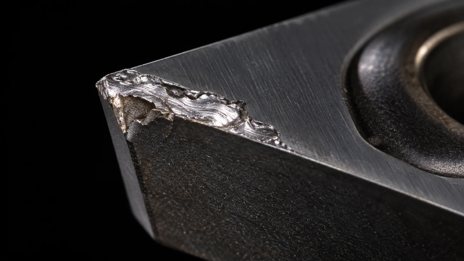
Look for material built up on the rake face or cutting edge, a smeared or torn surface, inconsistent chip flow, and a finish that changes after a short run. These clues are suggestive, not conclusive: built-up material can be difficult to distinguish from a chipped edge or coating damage, and a rough finish can result from runout, chatter, poor chip evacuation, or a dull tool. Inspect the edge under suitable magnification and compare it with a clean known-good edge before assigning cause.
Record the alloy and temper from the material documentation. “Aluminum” is not a single cutting behavior; chemistry, temper, stock form, and prior processing can change how the material deforms and how chips form. The site’s panoramica sui materiali in alluminio is a starting point for separating material selection from the machining symptom.
Correlare il sintomo alla causa probabile
| What you observe | Checks to make first | Perché è importante |
|---|---|---|
| Edge has adhered aluminum and finish becomes smeared | Insert geometry, edge sharpness, speed/feed balance, coolant reaching the cut | Adhesion changes the effective cutting edge |
| One flute or tooth shows much more buildup | Tool runout, holder cleanliness, cutter damage, engagement distribution | Unequal chip load can overload a single edge |
| Problem begins in a pocket or deep feature | Chip evacuation, recutting, tool reach, coolant access | Trapped chips can be cut again and disturb the edge |
| Only one material lot behaves differently | Alloy/temper identity, stock source, surface condition, certificate and lot traceability | Changing material condition can alter chip behavior |
| Finish is rough but no adhesion is visible | Chatter, deflection, tool wear, runout, burr formation, inspection method | Not every aluminum finish problem is BUE |
Use the table to choose a test, not to jump to a setting. If the tool shows uneven wear, verify runout near the working end and check holder and spindle interfaces. If the issue is localized in a cavity, examine the toolpath and chip evacuation. If the material lot changed, confirm the actual grade and temper rather than assuming the purchase description fully defines the stock.
Check the edge, engagement, and heat
Tool geometry is a central control. A sharp, polished cutting edge designed for nonferrous work can reduce material adhesion compared with an edge that is blunt, damaged, or poorly suited to the cut. Coating and substrate selection also matter, but “coated” does not automatically mean “better for aluminum.” The application, edge preparation, and surface condition of the tool should fit the alloy and operation.
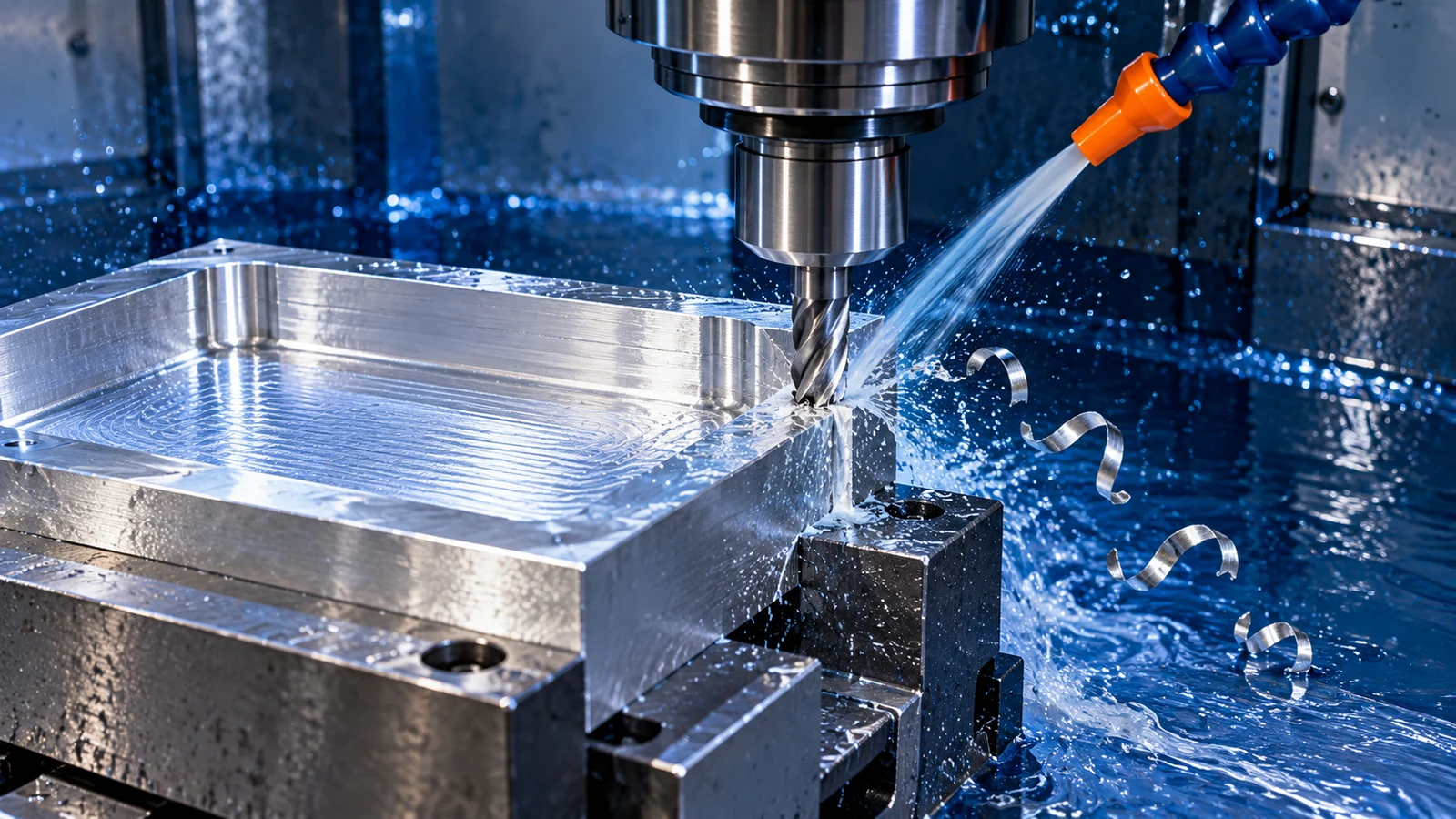
Cutting conditions must keep the edge shearing rather than rubbing. Too little chip thickness at a finishing pass, a worn edge, or a path that repeatedly dwells can promote smearing. On the other hand, a speed change alone cannot compensate for poor tool geometry or unstable engagement. Review speed, feed per tooth, radial and axial engagement, entry strategy, and finish allowance together, then change one variable at a time.
Coolant and chip evacuation should be evaluated at the cutting zone. A fluid stream that reaches only the outside of a deep pocket may not prevent chips from packing around the edge. Air blast, through-tool delivery, or a different toolpath may be relevant depending on the machine, feature, and shop procedure; no single method is universal. The Capacità di fresatura CNC page provides process context, but the exact route must still match the part geometry and drawing.
Verify the result on the part
After a change, compare a defined surface and feature—not just the appearance of one chip. Check the specified dimensions, surface finish where called out, burr condition, and consistency across the relevant quantity. Use the same measurement location, instrument, and part condition before and after the adjustment. If the surface is functional, document its datum relationship and acceptance criteria.
For an RFQ or process review, provide the drawing revision, material grade and temper, quantity, affected surface, finish requirement, and any post-machining treatment. If cosmetic quality matters, identify the visible region and acceptable condition rather than writing only “no tool marks.” This helps the supplier evaluate cutting access and inspection without turning a subjective preference into an ambiguous pass/fail rule.
When BUE recurs, preserve a sample showing the edge and surface condition and compare it with a stable run. That evidence is more useful than a list of unrecorded parameter changes. The aim is a controlled, repeatable cut that meets the drawing—not a single visually improved piece.
Domande frequenti
Does aluminum always need a higher cutting speed to prevent BUE?
No. Speed can influence adhesion, but the result also depends on edge sharpness, chip thickness, tool geometry, material condition, engagement, and coolant access. Confirm the cause on the actual operation before adopting a setting.
Can a polished or coated cutter eliminate built-up edge?
It can reduce the tendency in a suitable application, but it cannot guarantee elimination. A dull edge, runout, trapped chips, rubbing, or a material change can still produce unstable cutting.
Is a torn aluminum surface proof of BUE?
No. Chatter, tool deflection, runout, chip recutting, and edge damage can look similar. Inspect the tool and compare the location and pattern of the surface defect before deciding.