
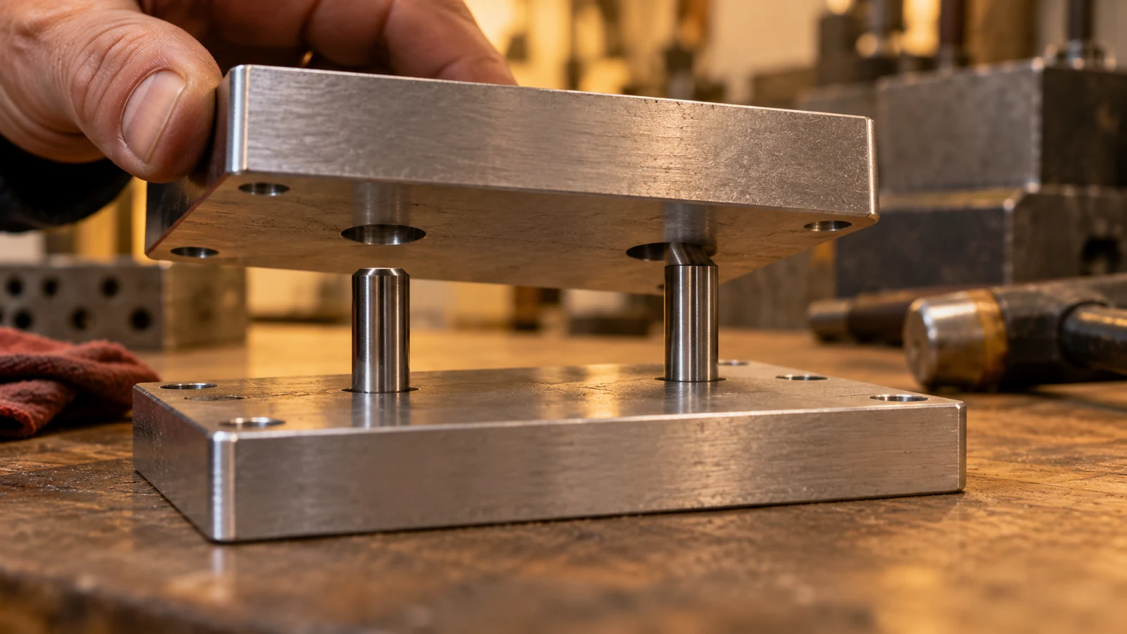
A hole pattern can pass individual X and Y checks yet refuse to assemble. The usual missing question is not just where each hole center lies on a coordinate sheet, but where each hole axis lies relative to the part’s assembly datums—and whether the holes work as a pattern. A position tolerance gives the designer a way to state that relationship, provided the datum scheme, basic dimensions, hole sizes, and inspection method are all clear.
This guide addresses true position for CNC-machined hole patterns. It focuses on drawing interpretation, machining setup, and acceptance evidence rather than repeating the broader introduction to GD&T on CNC drawings. Where a drawing follows ASME Y14.5 or another standard, use the specified edition and its actual feature-control frame; the simplified examples below are explanations, not substitutes for the controlled drawing.
Begin with the assembly failure
Consider an illustrative plate with four clearance holes and two locating dowel holes. A machinist measures each clearance hole from a convenient raw edge. Every coordinate looks acceptable, but the plate will not sit over the dowels in the mating assembly. The coordinate readings may be real; the reference edge may simply not represent how the part is located in use. This is an illustrative design-review scenario, not a customer case or a report of JUCHENG production results.
The engineer should first identify which surfaces and features constrain the plate in assembly. A mounting face might establish the primary orientation; a bore or side face might set lateral location; another feature might stop rotation. Only then can the position of the clearance-hole pattern be judged against the correct reference frame. If the mating part floats on clearance fasteners rather than locating pins, the needed positional control may be different.
Do not automatically tighten every hole coordinate because assembly failed once. The problem may be datum selection, hole size, an unexpected burr, coating build-up, or a second part that was never included in the stack-up. A position callout works best when the drawing makes the functional relationship explicit.
Read four parts of the position requirement
Before quoting or programming a pattern, read the requirement as four connected elements. Missing one can change the acceptance decision.
| Element | What it answers | Common ambiguity |
|---|---|---|
| Basic dimensions | Where is the theoretically exact pattern? | Coordinates are treated as independent plus/minus limits. |
| Feature-control frame | What positional zone and modifiers apply? | A diameter symbol or material-condition modifier is overlooked. |
| Datum references | What establishes the measurement frame? | Inspection aligns to a convenient outside edge instead of the specified datums. |
| Hole size and depth | What feature of size is evaluated, and over what extent? | Only one mouth of a long hole is checked while the axis tilts. |
For a cylindrical hole, a diameter symbol in the positional frame indicates a cylindrical tolerance zone for the derived axis under the applicable drawing rules. Do not replace that with separate X and Y limits without analyzing the resulting acceptance region. Likewise, a material-condition modifier may allow a different effective positional allowance as hole size changes; it should never be assumed from the word “true position” alone.
One pattern can have more than one functional relationship: the entire group may need to locate to a housing while the holes also need close spacing to one another. Advanced pattern controls can express those needs, but the drawing should be reviewed under its chosen standard rather than simplified into a generic “tight hole tolerance.”
A useful calculation—and its limits
For a simple two-dimensional illustration at one measured cross-section, let the measured hole-center offsets from basic location be ΔX and ΔY. The radial offset is √(ΔX² + ΔY²); a common diametrical position expression is 2√(ΔX² + ΔY²). If ΔX is 0.03 mm and ΔY is 0.04 mm, the radial offset is 0.05 mm and the corresponding diametrical value is 0.10 mm.
That calculation explains why two individually small coordinate deviations can produce a larger reported position value. It is not, by itself, a complete GD&T inspection. It does not establish the datum reference frame, evaluate the entire hole axis through thickness, account for applicable material-condition rules, or determine whether the measured feature fits a functional gauge. The illustrated numbers are arithmetic examples, not CNC capability claims or recommendations for a specific tolerance.
For a real drawing, ask the inspector to identify the actual datum alignment, evaluation method, measured feature representation, and any bonus or datum shift allowed by the specified standard. A spreadsheet of XY centers without those assumptions can be persuasive and still answer the wrong question.
Carry the datum scheme into machining
Process planning should start from the surfaces that represent the drawing datums. If those surfaces cannot be used directly for workholding, the manufacturing plan needs an explicit transfer: create stable references, locate the next setup repeatably, and keep chips and burrs away from the contact points. The more times the part is removed and reclamped, the more important that transfer becomes.
Hole location can be affected by more than the programmed center. Workpiece movement, tool walk at entry, cutter deflection, stock variation, thermal drift, and a weak wall around the pattern can all matter. A finishing operation may improve size or form without correcting a poorly established location. For process-level choices such as drilling, interpolation, boring, and reaming, consult the site’s CNC hole machining overview.
If the datum features themselves are machined, plan the order deliberately. Machining the holes first and creating a critical locating face later may produce a different datum relationship from the one the drawing requires. A single setup can help preserve relationships, but it is not automatically superior if the part lacks stiffness or tool access. The setup should be evaluated against the functional features, not against an arbitrary goal of minimizing operations.
Measure the same relationship the drawing controls
A caliper can measure many outside dimensions, and pin gauges can check certain hole sizes, but neither automatically proves a datum-related position tolerance. The inspection plan must establish the datum reference frame and determine the hole axes or other required derived features. Depending on the drawing and tolerance, a suitable CMM, functional gauge, or other qualified method may be used. The method must be agreed for the specific part; a machine name alone is not evidence of conformance.

Review the report as a traceable chain: drawing revision, datum setup, basic coordinates, feature size, measured locations, any applicable modifier, calculated positional result, and acceptance rule. If the report shows only “position = pass,” the buyer cannot easily determine whether the inspector checked the same relationship the assembly depends on. The broader CNC machining tolerances guide explains how function, limits, and verification should be connected.
Inspect after the processes that can change the final feature, when the drawing calls for that state. Deburring and coating can alter a mating condition; a thin plate can move when released from a fixture. If restrained-state inspection is required, state the restraint. If the drawing calls for a free-state result, do not use a fixture to conceal distortion.
Questions to resolve before release
- What actually locates the assembly? Mark the mating datums and decide whether the pattern is located by dowels, a bore, a pilot, or another feature.
- Which drawing standard and edition apply? Do not mix interpretations of position and material-condition rules from different systems.
- Do basic dimensions fully locate the pattern? Confirm that hole-to-hole spacing and pattern-to-datum location are unambiguous.
- Does the position control apply to every hole? Make the pattern callout, count, and exceptions explicit.
- How will the requirement be proven? Specify the inspection condition and the report or functional check needed for acceptance.
These questions are worth resolving before a supplier fixes the program and before a buyer compares quotations. If the controlled drawing leaves them unanswered, request a drawing clarification instead of asking a shop to guess the intended assembly datum. The site’s quality page provides company context; any project-specific gauge or report still needs confirmation.
Hole-pattern position FAQs
Is true position the same as a plus/minus coordinate tolerance?
No. A position control uses the drawing’s basic location, datum reference frame, tolerance-zone shape, and any applicable modifiers. Separate coordinate limits can permit a different region of variation.
Can all holes pass size but the pattern fail position?
Yes. Size and location are separate characteristics. A hole can accept a pin on its own yet be misplaced relative to the mating pattern or datums.
Does a CMM automatically prove assembly fit?
No. It can measure the specified geometric relationship when programmed and aligned correctly. Functional fit may also depend on the mating part, fastener clearance, burrs, coating, and the applicable material-condition rules.
Should a buyer request the raw XY readings?
They can be useful diagnostic data, but ask for the datum alignment, hole size, evaluation method, and positional result as well. Raw coordinates without a reference frame do not establish conformance.