
PEEK and PTFE solve different engineering problems. Choose PEEK when a machined component must retain load-bearing geometry under sustained stress; choose PTFE when low friction, chemical exposure, or non-stick behavior is the governing requirement and the design can tolerate more deformation. Neither label alone settles the decision: filled and unfilled grades, stock form, temperature, contact pressure, mating surface, and the actual drawing limits all matter.
For a CNC part, the useful comparison is not a generic property contest. It is whether the material can preserve the feature that makes the assembly work: a bore, sealing face, bearing surface, or locating shoulder. The PEEK material overview and PTFE material page are starting points; the selected grade and operating conditions still need to be specified.
Start with the loaded feature
Write down what the part must continue doing after hours or months in service. If a bearing block, guide, or insulator has to keep a close bore-to-shaft relationship under load, creep and stiffness deserve more weight than a headline friction value. If the part is a seal, liner, or chemically exposed slide, friction and chemical compatibility may dominate while dimensional movement can be accommodated by the assembly.
Also distinguish contact from structure. A thin PTFE wear face backed by a rigid carrier is a different design from a thick, unsupported PTFE bracket. Likewise, a PEEK component may be a structural member in one design and only a chemically resistant spacer in another. Material choice follows the load path and the geometry, not the application label.
When the fit must stay put
PEEK is commonly selected where a polymer has to carry load while preserving shape better than a very compliant fluoropolymer. That does not make every PEEK grade dimensionally identical. Reinforcement, bearing additives, stock manufacturing route, moisture and thermal history, and the thickness removed during machining can change how a component behaves. A drawing that calls only for “PEEK” may leave the supplier and inspector guessing about the intended grade.

PTFE can deform under sustained contact pressure. In a seal or low-load sliding interface, that compliance may be useful; around a precision locating feature it can instead relax preload or shift the effective clearance. If PTFE remains the better chemical or friction choice, the design can respond with a larger support area, a metal or PEEK backing structure, a replaceable wear element, or a fit that is less sensitive to small movement. Validate the assembled geometry under representative load and temperature rather than assuming an unloaded machined dimension predicts service behavior.
For close fits, specify which surfaces are functional and how the part is supported during measurement. A polymer can move with clamping force and temperature, so inspection conditions should be consistent with the drawing and the intended assembly—not an improvised “tight tolerance” detached from use.
When sliding or chemistry dominates
PTFE’s low-friction and chemical-resistance profile makes it attractive for sliding, sealing, and chemically exposed parts. Its low strength relative to structural engineering plastics is the trade-off. A mating surface can also dominate wear: a rough, sharp, or contaminated counterface may damage the polymer regardless of its catalog description. Review counterface finish, contact pressure, movement, lubrication, and whether particles can become trapped.
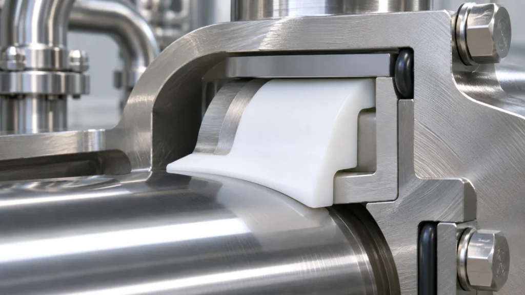
PEEK may be the better choice when the same part must support load and resist wear, especially when the interface cannot be given a separate carrier. But a generic “PEEK” request can hide meaningful differences between unfilled, carbon-filled, glass-filled, and bearing grades. Fillers can improve one property while changing wear against a particular counterface, machining behavior, surface quality, or electrical characteristics. Match the exact grade to the contact pair and environment.
For either polymer, check chemical compatibility against concentration, temperature, exposure duration, and stress. A compatibility chart is a screening tool; it is not a service-life guarantee for a stressed, machined component.
Machining changes the comparison
Machined plastics respond differently from metals. PTFE’s softness and tendency to deform can make thin walls, sharp corners, and clamping-sensitive features difficult to hold consistently. PEEK is more rigid, but stock condition, residual stress, heat, tool sharpness, and the order in which features are cut still matter. A deep bore released from a fixture may not measure exactly like the same bore while constrained.
Share the part’s functional datums, wall thicknesses, mating components, and the surfaces that control assembly. Agree whether a feature is measured after the part has stabilized and in what orientation. If the design needs a close fit, provide the mating size or fit range instead of asking the machine shop to infer it from an isolated nominal dimension. The CNC materials guide can help organize material questions before the drawing is released.
A practical selection table
| Part condition | Initial direction | What must be checked |
|---|---|---|
| Loaded locating bore or spacer | Evaluate PEEK first | Grade, sustained load, temperature, stock form, and assembled clearance |
| Low-friction seal or chemically exposed slide | Evaluate PTFE first | Pressure, support, counterface, movement, and deformation allowance |
| Wear part with both load and sliding | Compare exact bearing grades | Counterface, wear mode, filler, heat, debris, and replacement strategy |
| Thin-wall or highly constrained component | Review geometry before choosing | Clamping response, wall support, datum scheme, and inspection state |
This is a screening table, not a universal ranking. If the part sees combined chemical, thermal, and mechanical exposure, test the chosen grade in a representative assembly or obtain material-specific engineering guidance.
What to put on the RFQ
Name the polymer grade and supplier designation where the design depends on it; state whether unfilled or reinforced material is acceptable; identify the working fluid and temperature range; describe load, movement, mating surface, and expected life; and mark the dimensions that control assembly. If substitutions are permitted, define the evidence required before approval. A generic alternative-material note can change creep, fit, wear, or chemical performance in ways that are invisible at incoming inspection.
The useful answer is therefore conditional: PEEK is usually the stronger starting point for a load-bearing geometry, while PTFE is often the more natural starting point for low-friction or chemical service. The drawing and operating conditions decide whether that first choice survives review.