
For a machined plastic part that must locate accurately, POM is usually the more sensible starting point; for a sliding wear strip, liner, or guide where impact tolerance and abrasion behavior dominate, UHMW-PE often deserves the first look. The distinction is functional: POM tends to support stiffer, more dimensionally controlled features, while UHMW-PE is valued for tough, low-friction wear service. Neither is automatically the better material for every bearing or moving part.
First clarify what “POM” means on the drawing. POM-C and POM-H are distinct acetal grades, and “Delrin” is a trade name often associated with homopolymer acetal rather than a universal synonym for every POM. UHMW-PE also varies by stock grade and formulation. Compare the exact stock against the part’s load, movement, temperature, mating surface, and tolerance needs.
Define what the part has to do
“Plastic bearing” is not a complete duty description. A precision bushing that sets shaft position, a replaceable conveyor guide, and a sacrificial wear pad all experience contact, but the cost of movement is different. In the bushing, clearance growth can create runout or noise. In the guide, predictable wear and easy replacement may matter more than holding a close bore.
Describe whether the motion is continuous or intermittent, whether the contact is rolling or sliding, and whether load is steady or impacts occur. Include the mating material and finish, contamination, cleaning chemicals, and thermal environment. This often separates POM from UHMW-PE faster than comparing general-purpose property summaries.
For a fit that must remain controlled
POM is generally a better candidate when the component needs a relatively stiff, machined geometry: a locating bore, gear-like feature, fixture component, or spacer whose dimensions influence a neighboring part. That is a starting point, not a tolerance promise. The stock grade, section size, machining sequence, clamping, temperature, and measurement method all affect what can be held repeatably.
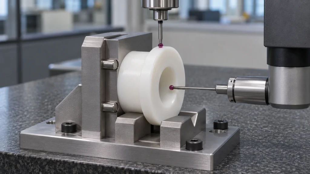
Specify the acetal family and grade. If homopolymer and copolymer are both acceptable, make the substitution rule explicit; if not, name the required type. The site’s POM material page and its POM-C grade page are useful starting points, but they do not replace the drawing’s acceptance criteria.
UHMW-PE can be machined into accurate parts, yet its high toughness and compliance make it a less natural default for a feature whose function depends on rigid location. Thermal expansion and elastic movement can become visible as a fit shift between inspection and service. If it is selected for a precision interface, define the functional clearance and verify the assembled behavior under expected load and temperature.
For sliding contact and impact
UHMW-PE is widely used for liners, guides, and wear surfaces because it combines toughness with good sliding and abrasion behavior. It can tolerate impacts that might damage a more brittle contact part. But “wear resistant” is not a result without conditions: abrasive particles, contact pressure, speed, counterface finish, alignment, and temperature all influence wear. A guide that runs dry against a rough edge can fail for reasons that a datasheet comparison does not capture.
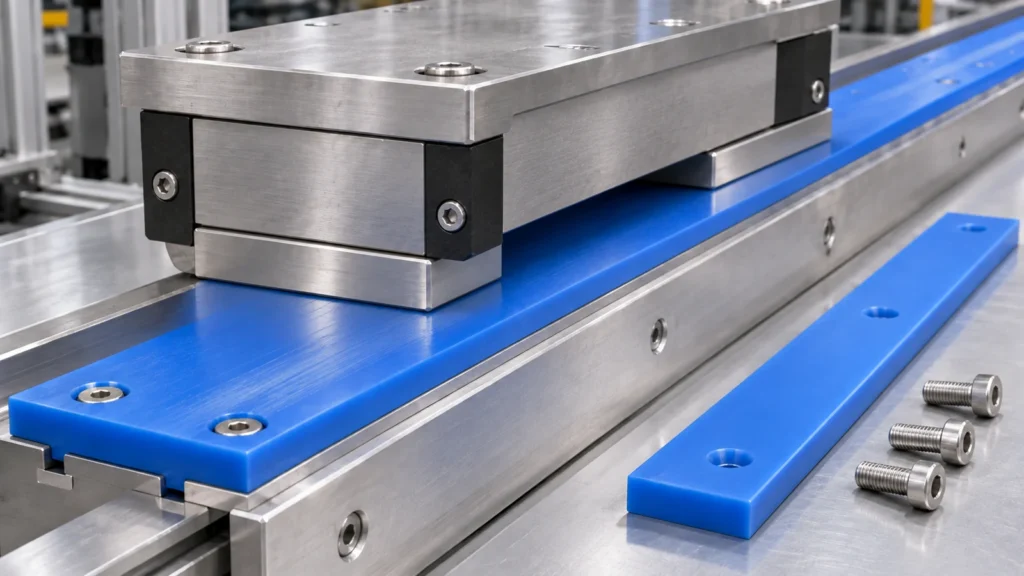
POM is also used in sliding components and can be a better choice when stiffness, shape retention, or lower friction in a specific design is important. The material pair should be evaluated together. A smooth metal shaft, a rough molded surface, and a contaminated conveyor track are not equivalent counterfaces. Where wear life is critical, prototype the actual contact geometry or define a measurable replacement limit.
The counterface and motion may decide
Separate bearing pressure from impact. A material that handles an occasional shock may still deform under a constant load. Likewise, a low-friction material can show rapid wear if it traps abrasive debris. For reciprocating motion, direction changes and edge loading matter; for continuous travel, heat buildup and debris evacuation may matter more.
Look at the whole interface: shaft hardness and finish, lubrication, contact width, edge radii, and whether the polymer can expand freely. If the part is a replaceable wear item, design its mounting and inspection around easy replacement. If it is a precision locating part, prioritize datum stability and control the relationship between the bore and mounting faces. The CNC material-selection overview helps frame those route questions without treating polymers as interchangeable.
Compare the engineering trade-offs
| Decision factor | POM / acetal | UHMW-PE |
|---|---|---|
| Primary design tendency | Stiffer, more controlled machined features | Tough sliding and wear surfaces |
| Fit sensitivity | Often the easier starting point for locating features | Check compliance, thermal movement, and sustained-load deformation |
| Impact and toughness | Depends on grade and geometry | Often favored for impact-tolerant wear applications |
| Machining concerns | Grade, heat, stress release, and clamping | Tool sharpness, support, heat, and elastic movement |
| Typical drawing risk | Calling a trade name without specifying grade | Using a wear-strip material where rigid location is essential |
These are broad selection tendencies. Supplier datasheets for the exact grade, stock form, and test method should govern numerical comparisons. Typical coupon properties do not guarantee a finished component’s tolerance or life.
Make the drawing specify the real requirement
Identify the surfaces that locate the assembly and the surfaces expected to wear. Give the mating part or working clearance, load direction, motion, cleaning environment, and any temperature range relevant to fit. State whether the material is POM-C, POM-H, a named UHMW-PE grade, or an approved equivalent, and describe how a substitution is reviewed. For traceable material control, define the required certification and lot records in the purchase specification.
Choose POM when controlled geometry is the priority; choose UHMW-PE when tough sliding wear service leads the decision. If a component must do both, design the load path and counterface first, then compare specific grades against the actual assembly instead of relying on the family name.