
A copper busbar drawing should not call for “flatness” without identifying the contact area, reference, condition and acceptance method. The functional question is whether the specified mating faces assemble with the intended contact and clamping arrangement—not whether every square millimeter of the bar is polished or perfectly planar. Define the contact patch or land, the relevant datum relationship, the surface condition after machining or plating, and any burr or edge restrictions. Electrical performance also depends on joint design, material condition, oxide and contamination control, pressure, fasteners and service environment. A machining flatness callout can help control the interface, but it cannot by itself guarantee contact resistance, temperature rise or current capacity; those belong to the electrical and assembly design requirements.
Identify the actual contact land
Mark the region that mates to another conductor, terminal or connector. A busbar may have holes, bends, steps, plated zones or local reliefs, so an overall-face requirement can be misleading. The drawing should show the usable contact land and its relationship to bolt holes, edges and any adjacent insulation or support. Where more than one joint face exists, identify each separately rather than relying on a general note.
Contact occurs at microscopic high points even when two faces appear to touch over a broad area. Joint pressure, surface films, contamination and finish all influence the real electrical interface. For that reason, flatness is only one part of the mechanical definition. Specify assembly pressure or torque only under the approved joint design and fastener procedure; do not derive it from a machining note.
The site’s copper material information provides background on copper grades and applications, while this drawing question is specifically about defining and verifying the machined mating face.
Choose a datum and flatness requirement
Set a datum scheme that represents how the busbar is supported and joined. If a face seats against a rigid mating component, that interface can guide the reference strategy. If the bar is thin or flexible, the inspection condition matters: a free-state measurement can differ from a supported or clamped state. State the condition whenever support or restraint can change the measured shape.
Use a flatness control only when the form of that surface itself is the design requirement. If the functional need is the face’s orientation to a hole pattern, bend, or other mounting datum, a relationship control may communicate the intent better. The design authority should select the geometric control and tolerance based on the joint and stack-up; do not copy a universal flatness value from another busbar.
| Design question | Drawing information to resolve |
|---|---|
| Where does electrical contact occur? | Marked contact land, size and location |
| How is the part supported in service? | Datum references and free-state or restrained condition |
| What surface is delivered? | Machined, plated, cleaned or otherwise treated condition |
| How will acceptance be demonstrated? | Measurement coverage, method, sampling and report scope |
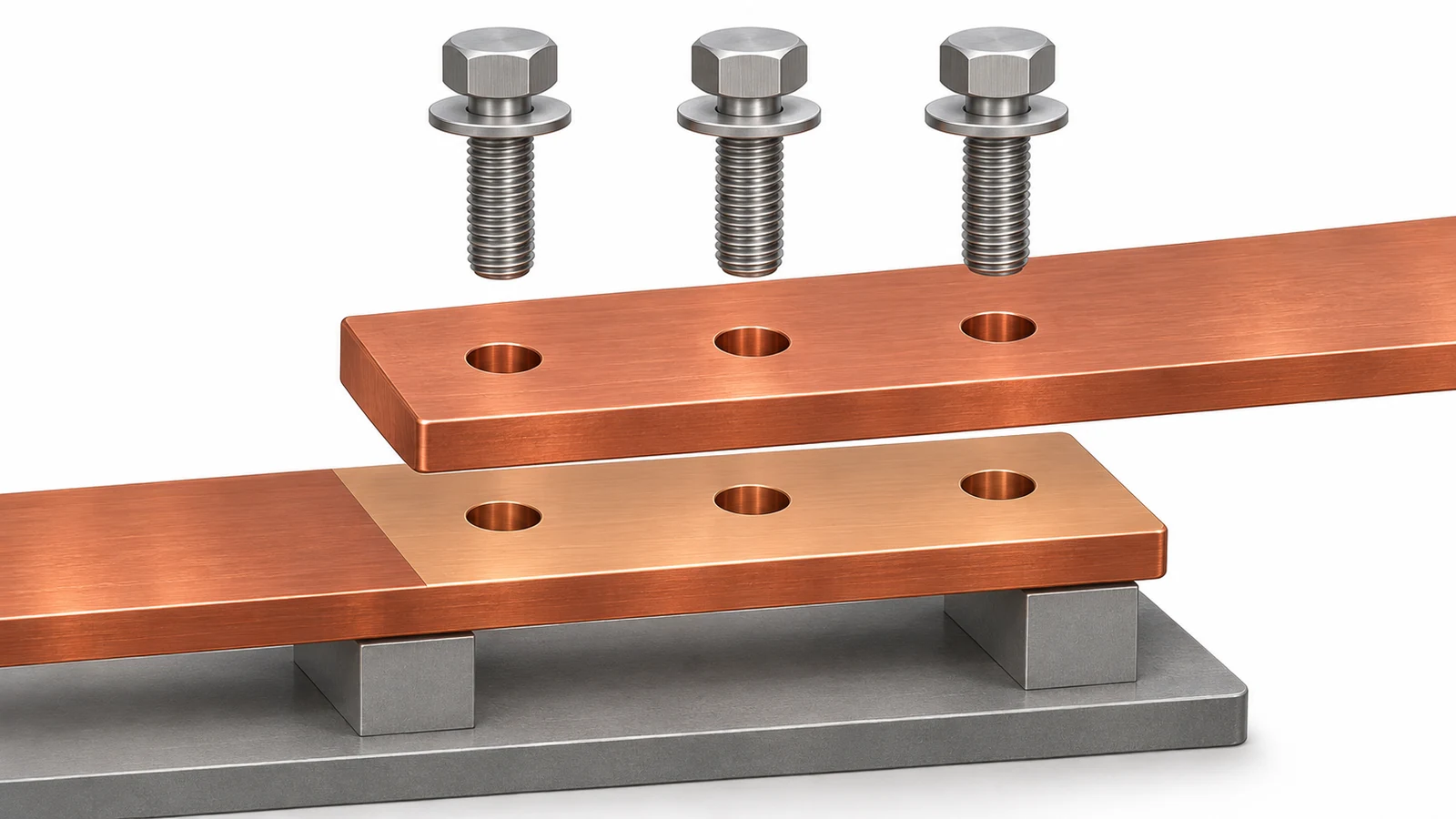
Control finish, burrs, and post-process condition
Surface texture should be specified on the faces that matter, with the parameter and measurement conditions defined where needed. Avoid substituting a visual description such as “smooth” for a measurable requirement. At the same time, an unnecessarily tight finish over the entire part can add cost without improving the joint. Localize the callout to the contact land and explain the functional purpose in the drawing notes.
Burrs around fastener holes and cut edges can prevent seating, damage insulation or create handling risks. Define edge treatment where it approaches the contact patch, but protect the land from uncontrolled rounding or hand polishing that changes the intended geometry. If plating or another finish follows machining, clarify whether dimensions and surface requirements apply before or after that operation, and who owns masking or final inspection.
Machining access and material behavior influence the route, but the drawing remains the acceptance authority. Related CNC milling and surface-finish information may help frame the manufacturing discussion without replacing the specified contact-face requirements.
Inspect the face without hiding the assembly problem
Choose a measurement method that samples the defined land and supports the part as intended. A straightedge or indicator can reveal gross variation but may not establish a tight form limit; a coordinate or surface measurement plan may be more appropriate depending on size, shape and tolerance. The inspection record should identify the support condition, measured area, instrument or method, and result. If the contact land is interrupted by holes or slots, state whether those regions are excluded from the evaluation.
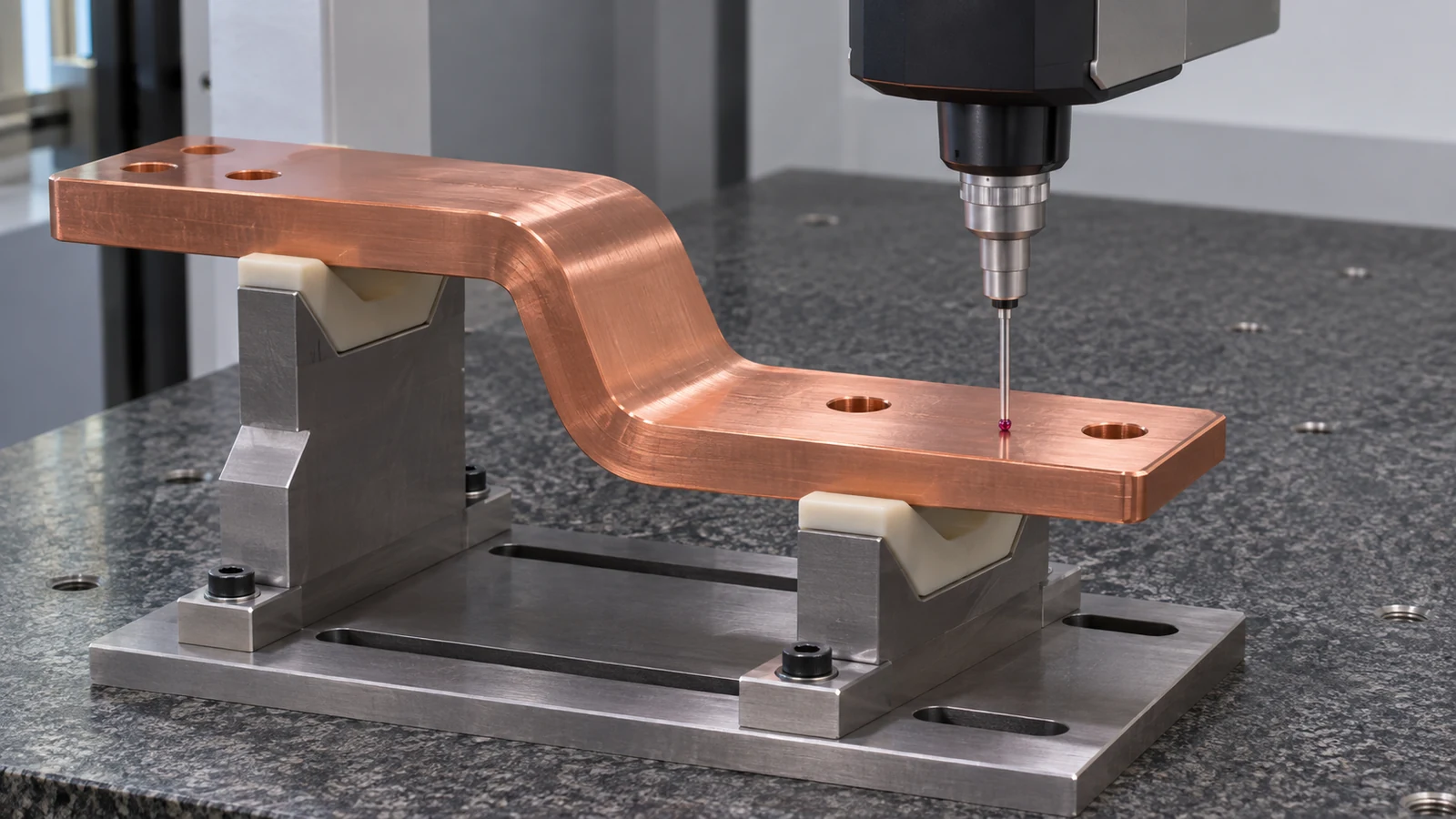
Inspect the face after the last operation that can alter it, including machining, deburring, cleaning or plating as applicable. A measurement before plating may not describe the delivered interface. Also verify that the fixture does not flatten a compliant part during measurement unless the drawing defines a restrained condition.
Where function depends on the assembled joint, a controlled assembly or electrical test may be required in addition to geometric inspection. Define the test circuit, contact preparation, fastener procedure and acceptance limit with the responsible electrical engineer. Do not infer electrical performance from a flatness result alone.
Keep machining acceptance separate from electrical qualification
Industry guidance on copper busbar joints emphasizes that contact condition and pressure affect the interface. It does not supply one machining flatness tolerance that applies to every geometry, current, fastener or environment. The drawing and joint specification must connect the selected contact surface to its service requirements, while the manufacturing inspection confirms only the characteristics assigned to it.
For a quote or first-article review, provide the material and temper, thickness, bend and hole geometry, contact-land marks, finish or plating sequence, support condition, datum scheme and required report. Keep electrical acceptance criteria under the electrical design authority. This division gives manufacturing a measurable face requirement without implying that machining alone qualifies the complete busbar assembly.