
For many shafts, arms, yokes, hubs, and high-load connectors, the real manufacturing route is forged blank plus CNC finishing. This guide starts from mechanical duty, then works backward to stock form, tooling, machining allowance, datum strategy, heat treatment, and inspection.
Replace “Which Is Stronger?” With “What Must Survive?”
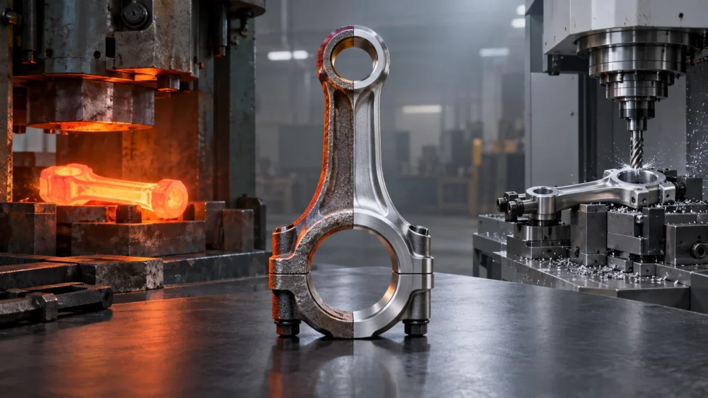 Strength is not one property. Yield, ultimate strength, fatigue, impact, fracture toughness, hardness, wear, and performance at temperature answer different questions. Geometry, surface condition, notches, residual stress, heat treatment, and loading direction can matter as much as nominal material values.
A forged preform may align grain flow around a shape and reduce disruption at highly loaded regions. A machined component made from appropriate stock can still perform very well, especially when its load path is simple and the stock condition is suitable. Machining from solid also gives designers flexibility to change geometry without new forming dies.
Define the failure mode before choosing the route. If a joint experiences repeated bending, a rotating shaft sees torsion, or an arm receives impact, the direction and concentration of stress should shape the material and process decision.
Strength is not one property. Yield, ultimate strength, fatigue, impact, fracture toughness, hardness, wear, and performance at temperature answer different questions. Geometry, surface condition, notches, residual stress, heat treatment, and loading direction can matter as much as nominal material values.
A forged preform may align grain flow around a shape and reduce disruption at highly loaded regions. A machined component made from appropriate stock can still perform very well, especially when its load path is simple and the stock condition is suitable. Machining from solid also gives designers flexibility to change geometry without new forming dies.
Define the failure mode before choosing the route. If a joint experiences repeated bending, a rotating shaft sees torsion, or an arm receives impact, the direction and concentration of stress should shape the material and process decision.
Let the Load Path Lead the Manufacturing Plan
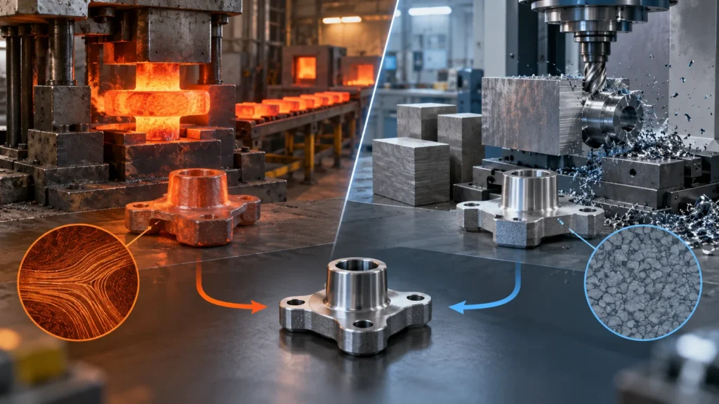 Mark where force enters, how it travels, and where it leaves. Identify section changes, fillets, splines, holes, shoulders, threads, and contact faces along that path. Features that interrupt flow or create stress concentration deserve special attention whether the part is forged or machined.
Forging can place material efficiently around the path and create a near-net envelope with favorable flow. It also brings constraints: draft, flash, parting line, die fill, section transitions, tooling access, and forming sequence. Machining can create precise detail and smooth controlled radii, but cutting across the stock’s existing grain orientation may not reproduce a forged contour.
Finite-element results are only as useful as their inputs. The model should use properties representative of the actual stock or forging condition, heat treatment, surface state, and load spectrum. Manufacturing choice should be part of design verification, not added after the stress report is complete.
Mark where force enters, how it travels, and where it leaves. Identify section changes, fillets, splines, holes, shoulders, threads, and contact faces along that path. Features that interrupt flow or create stress concentration deserve special attention whether the part is forged or machined.
Forging can place material efficiently around the path and create a near-net envelope with favorable flow. It also brings constraints: draft, flash, parting line, die fill, section transitions, tooling access, and forming sequence. Machining can create precise detail and smooth controlled radii, but cutting across the stock’s existing grain orientation may not reproduce a forged contour.
Finite-element results are only as useful as their inputs. The model should use properties representative of the actual stock or forging condition, heat treatment, surface state, and load spectrum. Manufacturing choice should be part of design verification, not added after the stress report is complete.
Billet and Forged Stock Are Not Opposites
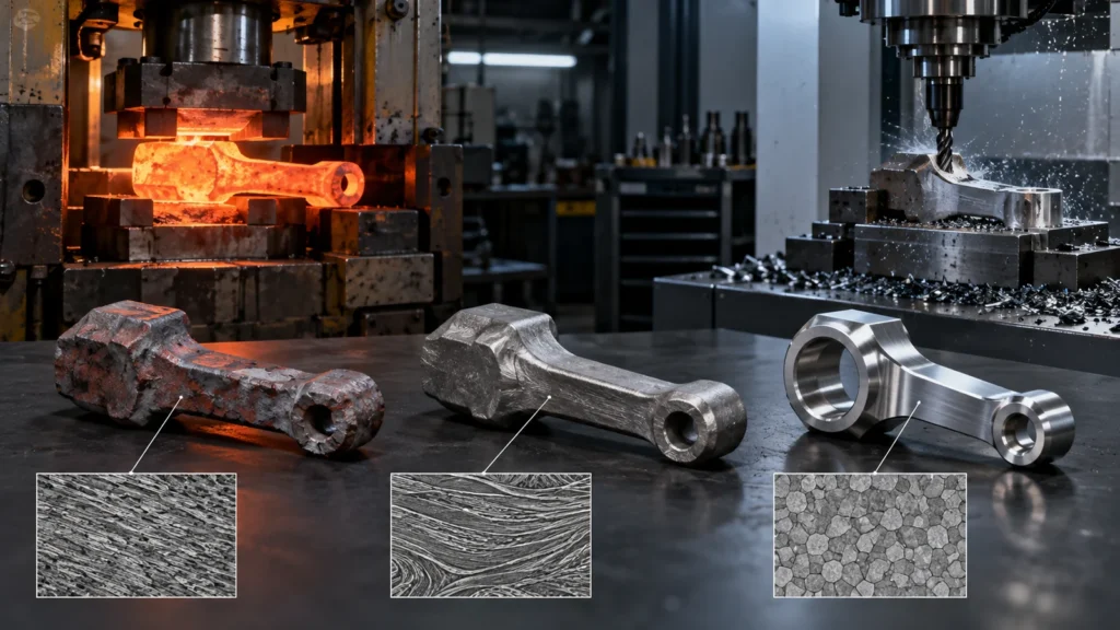 CNC machines cut whatever controlled starting form the route selects. That may be rolled plate, extruded bar, tube, cast blank, or forging. Therefore “forging versus CNC” often compares a primary shaping process with a finishing process rather than mutually exclusive alternatives.
Machining a simple prototype from billet can validate geometry quickly. Production may later move to a closed-die forging that leaves material for finish machining. Some programs continue machining from stock because demand, revisions, or geometry do not justify forming tooling. Others use an open-die or standard forged stock form without a dedicated near-net die.
Specify material standard, grade, stock or forging condition, heat treatment, and certification needs. The CNC 가공 소재 selection should be connected to the actual supply route rather than only the alloy name.
CNC machines cut whatever controlled starting form the route selects. That may be rolled plate, extruded bar, tube, cast blank, or forging. Therefore “forging versus CNC” often compares a primary shaping process with a finishing process rather than mutually exclusive alternatives.
Machining a simple prototype from billet can validate geometry quickly. Production may later move to a closed-die forging that leaves material for finish machining. Some programs continue machining from stock because demand, revisions, or geometry do not justify forming tooling. Others use an open-die or standard forged stock form without a dedicated near-net die.
Specify material standard, grade, stock or forging condition, heat treatment, and certification needs. The CNC 가공 소재 selection should be connected to the actual supply route rather than only the alloy name.
Geometry and Volume Set the Route Together
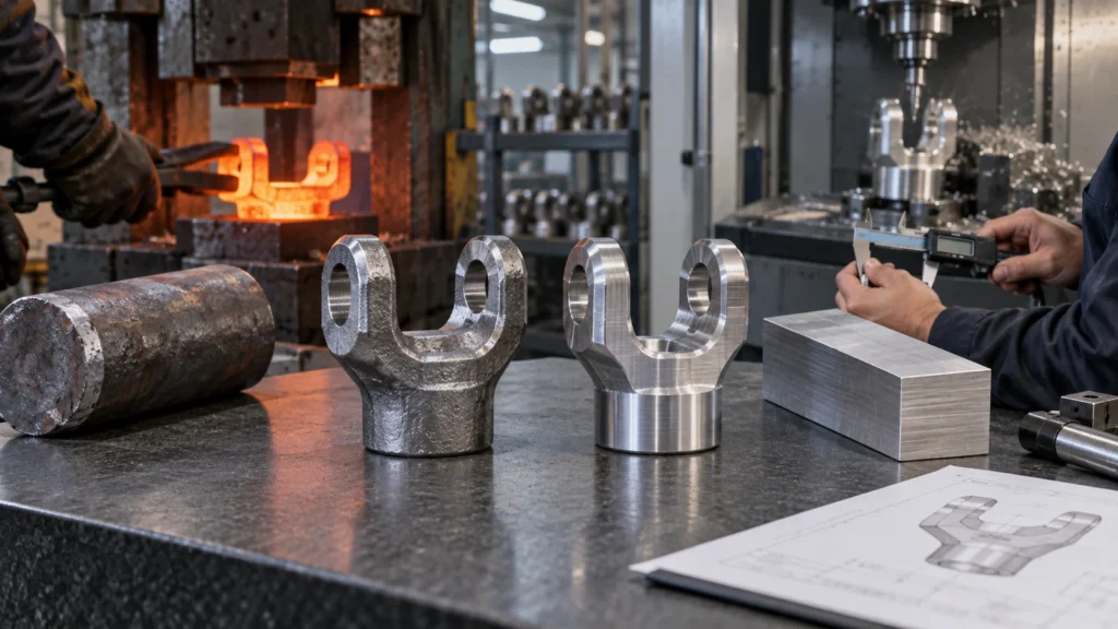
There is no dependable quantity threshold without the part. Tooling complexity, forging size, press availability, alloy, heat treatment, machining reduction, and forecast confidence matter. A high-volume part with little material removal may remain practical from stock; a moderate-volume expensive alloy shape may benefit from a preform sooner.
Planning a Forged-and-Machined Component
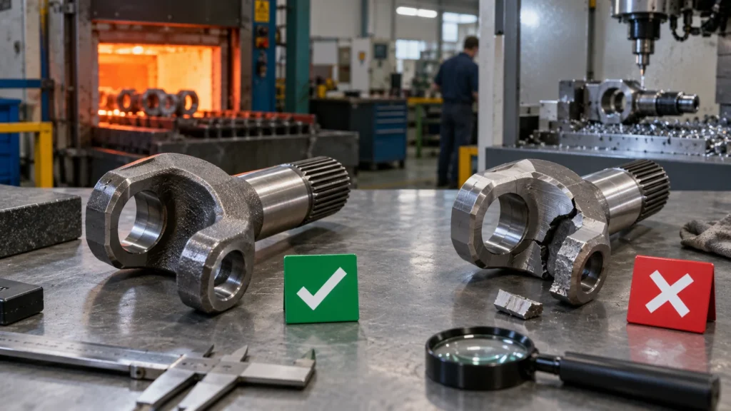 The forging drawing and finished-part drawing must work together. Define the forged envelope, parting and flash regions, draft, trim, scale removal, straightening if needed, and machining allowance. Provide robust locating pads or surfaces for the first operation. Allowance must cover forging variation while avoiding unnecessary cutting.
Datum strategy begins before the first finish cut. Initial workholding locates on a near-net shape; subsequent operations should transition to machined datums. If the forging twists or bows, the setup must distribute stock so all critical features clean up. Simulation and nominal CAD alone cannot replace physical allowance and locating review.
Protect grain flow where it matters. A forging advantage can be weakened if deep machining removes the beneficial outer flow or places critical surfaces in an unfavorable region. The forge and machine suppliers should agree on section cuts and material removal rather than optimizing their operations independently.
Flash trim and parting-line condition also affect machining. A parting mismatch or trim variation can interfere with clamping, consume allowance, or change how the first operation seats. The forging specification should identify areas that may contact fixtures and keep uncontrolled flash away from functional locating surfaces.
Handling protection begins at the rough-blank stage. Dents, scale, aggressive grinding, or mixed identification may later fall within a critical machined region. Mark high-risk surfaces and preserve lot identity before value is added through heat treatment and CNC work.
The forging drawing and finished-part drawing must work together. Define the forged envelope, parting and flash regions, draft, trim, scale removal, straightening if needed, and machining allowance. Provide robust locating pads or surfaces for the first operation. Allowance must cover forging variation while avoiding unnecessary cutting.
Datum strategy begins before the first finish cut. Initial workholding locates on a near-net shape; subsequent operations should transition to machined datums. If the forging twists or bows, the setup must distribute stock so all critical features clean up. Simulation and nominal CAD alone cannot replace physical allowance and locating review.
Protect grain flow where it matters. A forging advantage can be weakened if deep machining removes the beneficial outer flow or places critical surfaces in an unfavorable region. The forge and machine suppliers should agree on section cuts and material removal rather than optimizing their operations independently.
Flash trim and parting-line condition also affect machining. A parting mismatch or trim variation can interfere with clamping, consume allowance, or change how the first operation seats. The forging specification should identify areas that may contact fixtures and keep uncontrolled flash away from functional locating surfaces.
Handling protection begins at the rough-blank stage. Dents, scale, aggressive grinding, or mixed identification may later fall within a critical machined region. Mark high-risk surfaces and preserve lot identity before value is added through heat treatment and CNC work.
Heat Treatment Changes the Sequence
Heat treatment can occur before, between, or after machining stages depending on alloy, hardness, distortion risk, surface requirements, and final properties. Rough machining before heat treatment may remove bulk stock and leave allowance for distortion correction. Finishing after treatment may require different tools and parameters. Some features may need protection from decarburization, scale, or surface damage.
Sequence decisions affect datums and inspection. A bore finished before heat treatment may move; a thin wall may distort after stress release; grinding may be required after hardening. Define which dimensions are final at each state. Do not place final drawing limits on an intermediate operation without explaining their purpose.
Material traceability should connect forging lot, heat treatment batch, machining lot, and final inspection. This is particularly important where mechanical test results or special-process records form part of acceptance.
Evidence for High-Load Parts Goes Beyond Dimensions
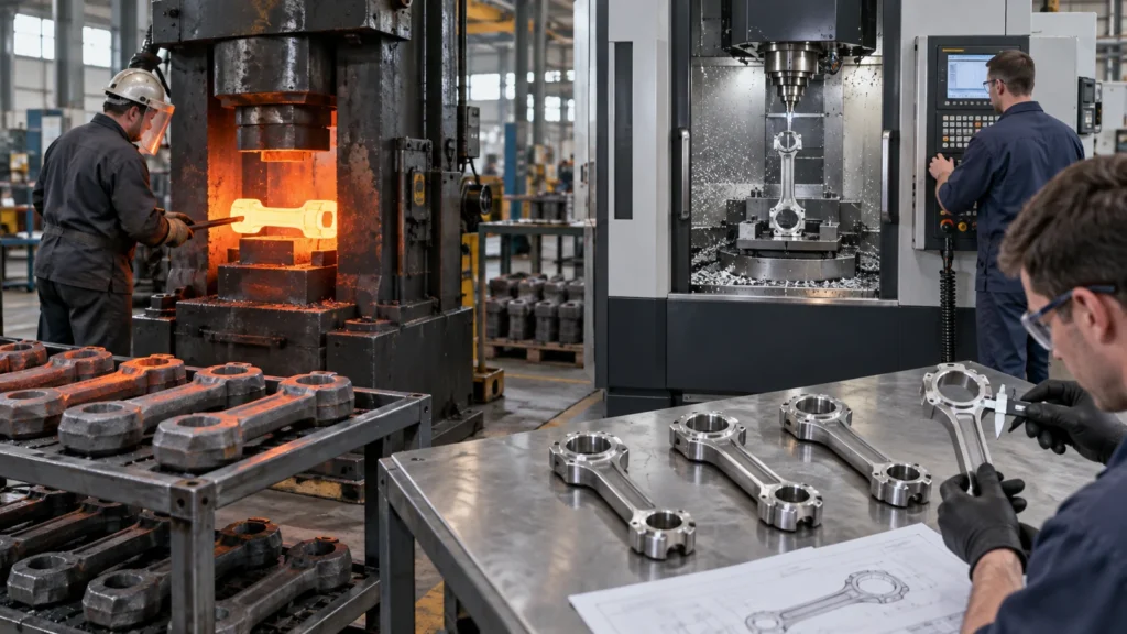 Dimensional inspection proves geometry, not internal quality or material condition. Depending on risk, the plan may include material certificates, heat-treatment records, hardness, mechanical tests, grain-flow studies, magnetic-particle or ultrasonic examination, surface integrity checks, and traceability. The applicable standard and acceptance criteria must be identified by the customer or engineering authority.
For machined-from-stock parts, verify stock orientation and certification where direction matters. For forgings, define sampling and examination regions. For both, protect high-stress surfaces from tool marks, burns, dents, or aggressive blending that could reduce fatigue performance.
The quality package should match consequence. Over-testing a benign bracket wastes cost; under-defining a rotating or safety-related part transfers risk downstream. The site’s quality capability overview can support supplier evaluation, but project-specific requirements still belong on the controlled documents.
Dimensional inspection proves geometry, not internal quality or material condition. Depending on risk, the plan may include material certificates, heat-treatment records, hardness, mechanical tests, grain-flow studies, magnetic-particle or ultrasonic examination, surface integrity checks, and traceability. The applicable standard and acceptance criteria must be identified by the customer or engineering authority.
For machined-from-stock parts, verify stock orientation and certification where direction matters. For forgings, define sampling and examination regions. For both, protect high-stress surfaces from tool marks, burns, dents, or aggressive blending that could reduce fatigue performance.
The quality package should match consequence. Over-testing a benign bracket wastes cost; under-defining a rotating or safety-related part transfers risk downstream. The site’s quality capability overview can support supplier evaluation, but project-specific requirements still belong on the controlled documents.
First-article approval should include more than one ideal sample when process variation matters. Review parts across cavities, die positions, heats, or production conditions as applicable. The objective is to understand the route’s normal variation before final machining fixtures and gauges are locked around a single favorable blank.
Supplier changes require controlled revalidation. A different forge source, heat-treatment route, stock orientation, or machining setup can alter evidence that was previously accepted. Define which changes require notification and which tests or records must be repeated.
Four Decision Cases
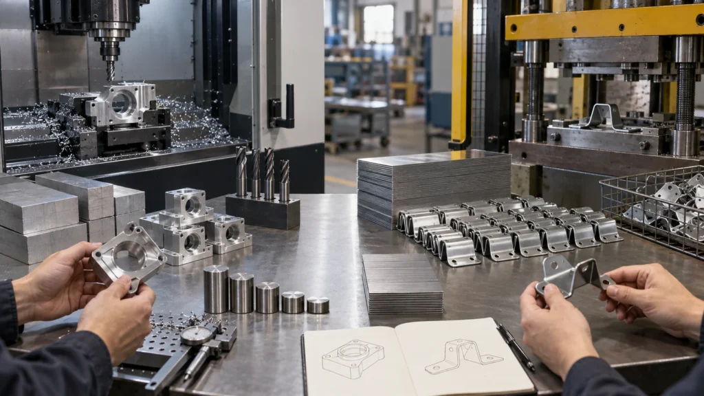
Machine from stock while pivot locations and clearances are changing. Use the prototype to confirm geometry, then reassess whether production loads and volume justify a forged blank.
High-duty yoke
A forged preform may align material around the arms and reduce stock removal. Finish-machine bores, faces, and threads from a datum plan tied to the near-net shape.
Precision housing
If performance is governed by dimensional interfaces rather than directional loading, billet machining may be simpler even at repeat quantities. Do not select forging merely for a generic strength claim.
Replacement shaft with uncertain demand
Machining from certified bar can avoid dedicated dies and inventory. A standard forged stock form may still be used if it meets the specification and supply need.
Procurement FAQs
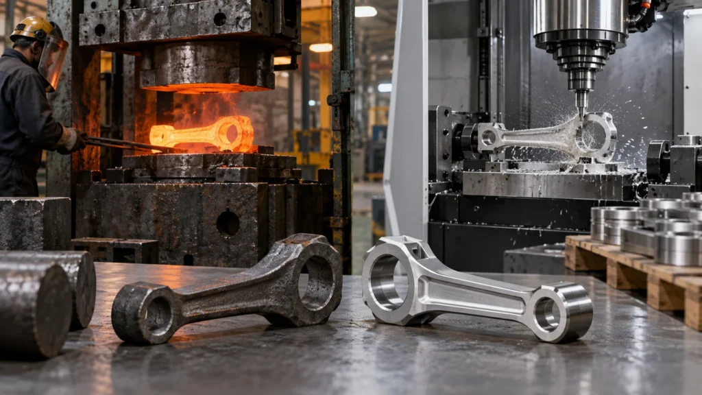
Machining removes material and can intersect the flow pattern of the starting stock or forging. Whether that matters depends on removal depth, flow direction, geometry, and loading. Review highly stressed regions with the material and forging specialists.
Can a forged part meet final tolerances without CNC?
Some noncritical features may remain as forged, but bores, fits, threads, sealing faces, and precise datums commonly need machining or grinding. Allocate requirements by feature.
When is billet best for production?
Billet can remain appropriate when design changes continue, quantities do not justify dies, geometry is machining-friendly, stock is readily available, or performance does not require a near-net forged flow pattern.
Who should own the allowance model?
It should be jointly agreed by forging and machining stakeholders, with clear design authority. The model must satisfy forging feasibility, cleanup, workholding, final geometry, and inspection needs.
These conditions explain why the advantages and disadvantages of CNC machining should always be evaluated against the complete manufacturing route.