
CNC machining design guidelines are most useful when they explain the tradeoff behind a feature, not when they present a single “safe” dimension without context. A pocket, slot, wall, or hole can be machinable in isolation and still force an extra setup, a long-reach tool, difficult chip evacuation, or an inspection problem. Before freezing a model, test the geometry against four questions: can the tool reach it, can the part be held, can the critical relationships be preserved, and can the result be measured?
Start with the setup plan
Every reorientation changes how the part is located and clamped. Multiple setups may be entirely appropriate, but each one adds a datum-transfer question: how will the next operation reproduce the relationship established earlier? A model with features spread across several faces can therefore require more than simply “one more toolpath.” It may need a fixture, a soft jaw, a probe routine, or an intermediate inspection.
Identify the surfaces that function as assembly datums and orient the part so the most important relationships can be produced from a stable reference wherever practical. If the design permits, keep related holes, faces, and slots accessible in one setup. Where that is not possible, define which relationships matter most and ensure the drawing makes them explicit.
For milling features, tool direction and part orientation are inseparable. The site’s CNC milling process guide provides process context; this design review focuses on changes an engineer can make before a quote or program is released.
Give tools a workable path
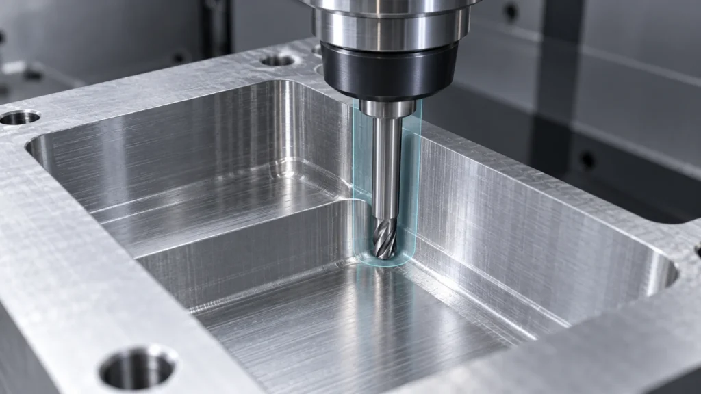 Deep narrow pockets, sharp internal corners, intersecting bores, and long slots can constrain tool diameter and reach. A small cutter may fit the geometry but be less rigid than a larger tool; extra reach can increase deflection and vibration risk. Internal corner radii that suit a standard cutter can reduce tool changes, while a corner that is intentionally sharp may require a secondary process or a design allowance.
Check not only whether a cutter can enter a feature, but whether it can clear chips, coolant can reach the cutting zone, and the tool can exit without colliding with nearby geometry. For a blind cavity, ask where chips will collect and how the bottom surface will be finished. For a cross-hole, determine whether the intersecting passage creates a burr location that can be reached for deburring or inspection.
Likewise, specify threads in a way that can be manufactured and verified. Thread depth, engagement, runout space, and proximity to a shoulder all affect access. Avoid adding thread depth beyond the functional engagement without a reason; the extra length may add tool time without improving the joint.
Deep narrow pockets, sharp internal corners, intersecting bores, and long slots can constrain tool diameter and reach. A small cutter may fit the geometry but be less rigid than a larger tool; extra reach can increase deflection and vibration risk. Internal corner radii that suit a standard cutter can reduce tool changes, while a corner that is intentionally sharp may require a secondary process or a design allowance.
Check not only whether a cutter can enter a feature, but whether it can clear chips, coolant can reach the cutting zone, and the tool can exit without colliding with nearby geometry. For a blind cavity, ask where chips will collect and how the bottom surface will be finished. For a cross-hole, determine whether the intersecting passage creates a burr location that can be reached for deburring or inspection.
Likewise, specify threads in a way that can be manufactured and verified. Thread depth, engagement, runout space, and proximity to a shoulder all affect access. Avoid adding thread depth beyond the functional engagement without a reason; the extra length may add tool time without improving the joint.
Design thin sections around their support
Thin walls and slender ribs are vulnerable to cutting forces, clamping pressure, and residual-stress release. The key question is not an isolated minimum thickness. It is how the wall is supported during roughing and finishing, how much material is removed from each side, and whether the geometry can be machined in a sequence that avoids loading a flexible section too early.
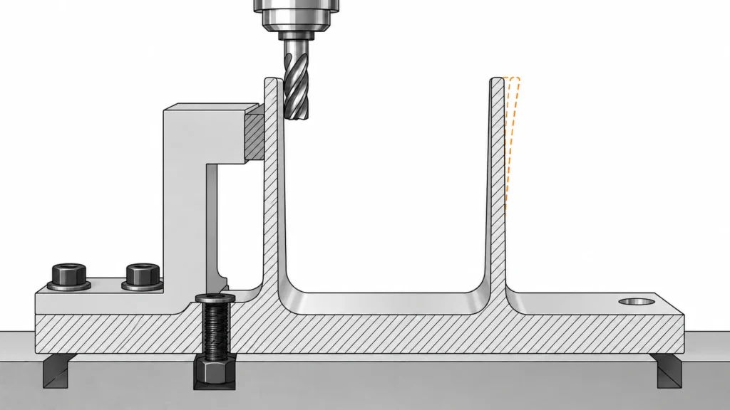 If stiffness is critical, consider adding temporary stock or sacrificial tabs that can be removed after the main features are machined. A wider base, a larger fillet, or a local rib may provide stiffness without changing the function of the part. If the wall must remain thin, identify it on the drawing and discuss measurement locations so that inspection does not unintentionally distort the feature.
A design with a large pocket behind a thin face should also consider how the face is clamped and inspected. A part may measure differently while restrained than after release. Avoid treating the vise or fixture as a permanent support when the final part will be free-standing.
If stiffness is critical, consider adding temporary stock or sacrificial tabs that can be removed after the main features are machined. A wider base, a larger fillet, or a local rib may provide stiffness without changing the function of the part. If the wall must remain thin, identify it on the drawing and discuss measurement locations so that inspection does not unintentionally distort the feature.
A design with a large pocket behind a thin face should also consider how the face is clamped and inspected. A part may measure differently while restrained than after release. Avoid treating the vise or fixture as a permanent support when the final part will be free-standing.
Make critical relationships inspectable
Precision is not improved by applying the tightest tolerance to every dimension. The drawing should distinguish functional requirements from general dimensions and define datums that reflect assembly or use. Position, profile, flatness, perpendicularity, and size controls answer different questions; selecting the wrong control can make inspection ambiguous even if the part appears to fit.
Think about measurement access while the CAD model is still flexible. Can a probe, pin, indicator, or CMM stylus reach the feature? Is there a stable surface from which to establish the datum? Will a finish, burr, or deep recess interfere with contact? If a measurement needs a special fixture or a particular sequence, indicate that requirement before production rather than after a report is disputed.
When a dimension is functionally critical, identify the mating condition or acceptance logic. The CNC machining tolerances article explains tolerance decisions; your drawing should make the required relationship explicit rather than relying on a supplier to infer intent.
A practical pre-release review
- Mark the primary locating faces and the features whose relationships must be maintained.
- Check tool reach, cutter diameter, corner radius, chip exit, and deburring access for every deep or intersecting feature.
- Review thin walls, long overhangs, and areas that may spring after unclamping.
- Separate critical dimensions from non-critical dimensions and state units and material clearly.
- Confirm that inspection can physically reach each controlled feature from a stable datum.
- Send a matching drawing and 3D model revision so manufacturing reviews the intended geometry.
This is not a checklist for eliminating every setup or forcing every part into a standard geometry. It is a way to expose the features that drive setup count, tool choice, workholding, and measurement. A design change is valuable when it preserves the function while reducing a real manufacturing or inspection constraint.
Frequently asked questions
Do design guidelines guarantee a lower machining cost?
No. A guideline identifies tradeoffs, but the result depends on the part, material, tolerance, quantity, and required finish. Review changes against function before releasing them.
Should every feature be machined in one setup?
No. A single setup may improve datum continuity, but it is not always feasible or economical. The goal is a controlled sequence with clear datum transfer and inspection.
Are standard internal radii always better?
They can allow common tools and avoid a sharp-corner operation, but radius selection must still suit the mating part, stress condition, and assembly function.
What model information should accompany the drawing?
Provide a 3D model that matches the drawing revision, plus units, material, finish, and any critical characteristics or inspection requirements not unambiguously conveyed in the model.