
En una era definida por la comunicación visual y el descubrimiento basado en datos, la claridad de una imagen o la estabilidad de un sensor puede ser la diferencia entre el éxito y el fracaso. Esta estabilidad fundamental, de la que dependen cámaras, telescopios, láseres e instrumentos topográficos, no es cuestión de azar. Es el producto de una ingeniería meticulosa y una precisión de fabricación. En el corazón de esta fiabilidad se encuentra un componente aparentemente simple pero críticamente complejo: el soporte para trípode. Esta interfaz especializada es el héroe anónimo, el punto de conexión literal que transfiere vibraciones, soporta peso y mantiene la alineación. El proceso de crear estos componentes vitales, conocido como mecanizado de soportes para trípode, es una disciplina donde la fabricación avanzada se encuentra con estándares mecánicos exigentes. Transforma el metal en bruto en una interfaz impecable y fiable, garantizando que, ya sea capturando una fotografía irrepetible o realizando un análisis geoespacial preciso, el equipo permanezca firmemente seguro y perfectamente orientado.
¿Qué es el mecanizado de soportes para trípode? Definición del estándar de interfaz
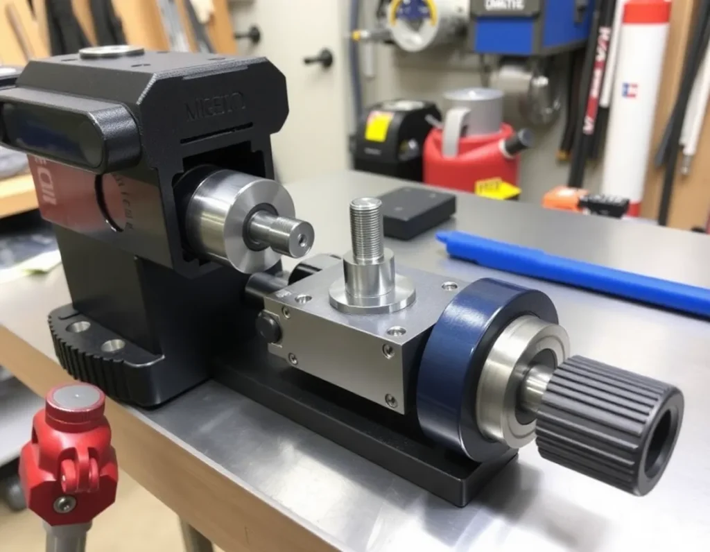
El mecanizado de soportes para trípode es el proceso de fabricación especializado de creación de roscas estandarizadas, placas y receptáculos que permiten fijar el equipo de forma segura a un trípode u otra plataforma estabilizadora. Es mucho más que taladrar un agujero; es la ingeniería y producción de un sistema de interfaz mecánica completo diseñado para un acoplamiento repetible, una alineación precisa y una fiabilidad de carga. Este proceso define el lenguaje universal entre un dispositivo y su soporte. Aunque se asocia comúnmente con la fotografía de consumo, el alcance del mecanizado de soportes para trípode se extiende a cualquier campo que requiera un montaje estable y desmontable para instrumentación. El proceso de mecanizado debe tener en cuenta la forma de la rosca, la profundidad, la concentricidad y la perpendicularidad de la superficie de montaje respecto al eje óptico o de medición del dispositivo. Un soporte mal mecanizado introduce holgura, desalineación e inestabilidad, degradando directamente el rendimiento. Por lo tanto, esta disciplina de mecanizado se centra en crear una interfaz perfecta y estandarizada que se vuelve funcionalmente invisible, permitiendo al usuario conectar el equipo con absoluta confianza en su rigidez y precisión.
La anatomía de un soporte para trípode: roscas, placas y receptáculos
Comprender el mecanizado de soportes para trípode requiere diseccionar los componentes principales del soporte. Cada elemento desempeña un papel distinto en la función global del sistema y debe mecanizarse según especificaciones exactas.
Roscas: el mecanismo de fijación principal
El receptáculo roscado es el elemento más fundamental. Los dos estándares dominantes son el 1/4″-20 UNC (Unified National Coarse) y el más grande y resistente 3/8″-16 UNC. El “20” y el “16” se refieren a las roscas por pulgada. El mecanizado de estas roscas implica crear una estructura helicoidal limpia y precisa con los diámetros mayor y menor correctos. La profundidad de la rosca y el grosor de la pared del receptáculo son críticos para la resistencia, especialmente en materiales como el aluminio. Un receptáculo con rosca cruzada o fuera de especificación puede fallar catastróficamente.
Placas de montaje y sistemas de liberación rápida
Para uso profesional e industrial, una conexión roscada directa suele ser demasiado lenta. Esto llevó al mecanizado de sistemas de liberación rápida, que constan de dos partes: una placa que se fija al dispositivo y un receptáculo en la cabeza del trípode. La placa, a menudo mecanizada en acero o aluminio, presenta una cola de milano o ranura de bloqueo precisa y un orificio roscado. La abrazadera de acoplamiento del trípode debe mecanizarse para coincidir con esta geometría sin holgura alguna. Las tolerancias aquí son excepcionalmente ajustadas, ya que cualquier holgura se traduce directamente en movimiento de la cámara o del instrumento.
Carcasas de receptáculos y refuerzo
El casquillo roscado o la abrazadera de liberación rápida no existe de forma aislada. Está alojado dentro de un componente más grande, ya sea la placa base de una cámara, el anillo tubular de un telescopio o la carcasa de un láser. El mecanizado implica integrar este receptáculo en el dispositivo anfitrión. Esto a menudo requiere crear un jefe reforzado o un inserto roscado (un helicoil o un inserto de latón prensado) para evitar el desgaste y el barrido de rosca en carcasas de metal más blando. La alineación del eje de este receptáculo con respecto al eje funcional del dispositivo es una consideración primordial durante la configuración del mecanizado.
Procesos de mecanizado esenciales para monturas de trípode: del CNC al laminado de roscas
La creación de una montura de trípode fiable emplea una secuencia de procesos de mecanizado avanzados, seleccionados en función del material, el volumen y los requisitos de precisión.
Fresado CNC: dar forma a la base
El fresado por control numérico por computadora (CNC) es el caballo de batalla para crear las placas de montaje, las carcasas de los receptáculos y los complejos mecanismos de liberación rápida. Una máquina CNC utiliza comandos programados para controlar las herramientas de corte con extrema precisión. Puede mecanizar la superficie de montaje plana, perforar el agujero piloto para la rosca y cortar los intrincados perfiles de una cola de milano de liberación rápida, todo en una sola configuración. Esto garantiza una alineación perfecta entre todas las características, lo cual es imposible de garantizar si las operaciones se realizan en máquinas separadas.
Taladrado y roscado con macho: crear el núcleo roscado
Para el casquillo roscado, el proceso comienza con el taladrado de un agujero piloto a un diámetro específico. A continuación, se realiza el roscado con macho, el proceso de cortar roscas internas. Esto se puede hacer con un macho manual en una taladradora de columna para volúmenes bajos, pero para lograr consistencia en la producción, las máquinas CNC a menudo utilizan el roscado rígido, donde la rotación del husillo y el avance vertical están perfectamente sincronizados para producir roscas limpias y precisas sin romper el macho.
Laminado de roscas: una alternativa superior para la resistencia
Para aplicaciones de alta resistencia, a menudo se prefiere el laminado de roscas al corte. Este proceso de conformado en frío utiliza troqueles endurecidos para desplazar el material hacia la forma de la rosca, en lugar de cortarlo. Esto da como resultado roscas con superficies más lisas, granos endurecidos por deformación (lo que aumenta la resistencia) y sin fibras cortadas que puedan iniciar grietas. Las roscas laminadas son más resistentes a la fatiga y duraderas, lo que las hace ideales para monturas de servicio pesado o de uso frecuente en entornos industriales.
Torneado y mandrinado en tornos CNC
Para componentes cilíndricos como insertos roscados o las perillas de sujeción para sistemas de liberación rápida, el torneado CNC es esencial. Un torno hace girar la pieza de trabajo mientras una herramienta de corte estacionaria le da forma. Este proceso es perfecto para lograr concentricidad y roscas externas lisas. El mandrinado se utiliza para agrandar y acabar un agujero existente a un diámetro y acabado superficial muy precisos, a menudo como paso preparatorio para prensar un inserto roscado.
Selección de materiales para durabilidad y rendimiento: aluminio, acero y compuestos
La elección del material en el mecanizado de monturas de trípode es un equilibrio crítico entre peso, resistencia, resistencia a la corrosión y maquinabilidad. El material incorrecto puede provocar un desgaste rápido de la rosca, agarrotamiento o fallo mecánico.
Aleaciones de aluminio: el estándar para equipos ligeros
El aluminio, en particular aleaciones como la 6061-T6, es omnipresente en la fotografía de consumo y la electrónica. Ofrece una excelente relación resistencia-peso, es altamente mecanizable y resiste la corrosión. Sin embargo, el aluminio es relativamente blando. El roscado y desenroscado repetido de un tornillo de trípode de acero en un casquillo de aluminio puede provocar desgaste y, finalmente, el barrido de la rosca. Para combatir esto, los mecánicos a menudo prensan un inserto roscado de latón o acero inoxidable más duro en la carcasa de aluminio, lo que prolonga drásticamente la vida útil de la montura.
Stainless Steel: For Corrosion Resistance and High Loads
Stainless steel alloys, such as 304 or 316, are chosen for applications where strength, durability, and resistance to harsh environments are paramount. Scientific instruments, marine equipment, and military hardware frequently use stainless steel mounts. While heavier and tougher to machine than aluminum, stainless steel provides exceptional thread durability and will not rust, making it ideal for field use in all conditions.
Carbon Steel and Alloy Steel: Maximum Strength
For the most demanding industrial applications—such as mounting large broadcast lenses, heavy laser cutters, or seismic sensors—high-strength alloy steels like 4140 or 4340 may be used. These materials can be heat-treated to achieve tremendous tensile strength. They are almost always used with a protective plating or coating (like nickel or zinc) to prevent corrosion. The quick-release plates on high-end tripod heads are often machined from these steels for their resistance to deformation and wear.
Advanced Composites and Titanium
In aerospace and high-end performance sectors, materials like titanium and carbon-fiber-reinforced polymers (CFRP) are machined for mounts. Titanium offers a strength-to-weight ratio superior to steel and excellent corrosion resistance but is challenging and expensive to machine. Composites are extremely light and stiff but require specialized machining techniques to prevent delamination and require metallic inserts to be bonded in to provide a durable threading surface.
Tolerances and Precision: Why Micron-Level Accuracy is Non-Negotiable
In tripod mount machining, “close enough” is a recipe for failure. The entire value of the mount lies in its ability to provide a rigid, repeatable connection with zero unwanted movement. This demands adherence to tolerances measured in microns (thousandths of a millimeter).
Consider the thread interface. A 1/4″-20 thread has defined tolerances for its pitch diameter. If the tapped hole is even slightly oversized, the mating screw will have lateral play, causing the equipment to wobble. If it’s undersized, the screw will bind or cross-thread, damaging both components. The perpendicularity of the threaded hole to the mounting surface is equally critical. If this axis is off by even a small angle, tightening the screw will induce a bending moment, pulling the device out of alignment and creating a point of high stress that can lead to failure.
For quick-release systems, the tolerances are even more extreme. The mating dovetail or Arca-Swiss style plate must slide smoothly into the clamp but, when locked, must have no detectable movement. This requires machining the locking groove and the clamp’s jaws to tolerances that ensure a seamless transition from free movement to absolute rigidity. Any imperfection in the surface finish or geometry results in “slop,” which at telephoto focal lengths or high-magnification microscopy renders the equipment unusable.
This precision is achieved through calibrated, high-quality machine tools, rigorous in-process inspection, and skilled machinists who understand the functional outcome of every dimension on the blueprint. The use of Coordinate Measuring Machines (CMM) and optical comparators to verify critical features post-machining is standard practice. In essence, the silent, unwavering stability we expect from a mounted device is purchased directly with micron-level precision in the machining process.
Applications Beyond Photography: Scientific, Industrial, and Military Uses
While the tripod mount is synonymous with cameras, its role as a universal, precision interface for stabilization and attachment is foundational across numerous high-stakes fields. The principles of mecanizado de soportes para trípode are directly applied to create reliable connection points for equipment where failure is not an option. In scientific research, vibration isolation is paramount. Laboratory-grade optical tables and breadboards are often equipped with a grid of precisely machined threaded holes, typically 1/4″-20 or M6, allowing researchers to securely mount lasers, mirrors, sensors, and microscopes. The repeatability and rigidity afforded by these machined mounts ensure that experimental setups are not only stable but also reproducible over time, a critical factor in longitudinal studies. In astronomy, telescope guide scopes, CCD cameras, and filter wheels all utilize standardized or custom tripod-style mounts to maintain perfect optical alignment despite temperature shifts and positional changes.
Industrial applications demand even greater robustness. Machine vision systems used in automated quality control on high-speed production lines rely on machined mounts to position cameras and lighting units with unerring accuracy. Any shift in the camera’s angle could lead to misidentification of defects, costing thousands in scrap or recalls. Similarly, in surveying and LiDAR scanning, the mounting interface between the scanner and its tripod or mobile platform must be machined to withstand environmental harshness while eliminating any play that would distort spatial data. The military and defense sectors push these requirements to the extreme. Equipment such as thermal imagers, rangefinders, and communication devices mounted on vehicles, aircraft, or carried by personnel use specialized, hardened mounts. These are often custom-machined from high-strength alloys with features like quick-release levers, anti-rotation pins, and sealing gaskets to protect against shock, vibration, dust, and moisture. The common thread across all these applications is the non-negotiable need for an interface that transforms separate components into a single, rigid unit, a need met by precision machining.
Design Considerations and Standards: 1/4″-20, 3/8″-16, and Custom Solutions
The design of a tripod mount is a balancing act between universal compatibility, mechanical strength, and application-specific needs. This has led to the establishment of dominant standards alongside a world of custom solutions. The most ubiquitous standard is the 1/4″-20 UNC threaded socket. This simple coarse thread, measuring 1/4 inch in diameter with 20 threads per inch, is the de facto connection for consumer cameras, many video accessories, and a vast array of lightweight scientific gear. Its prevalence makes it a default starting point for design. For heavier payloads, the 3/8″-16 UNC thread is the standard. This larger, stronger thread is commonly found on professional video tripod heads, large format cameras, and heavier industrial equipment. Many professional devices feature a dual-threaded receptacle—a 3/8″-16 socket with a removable 1/4″-20 adapter insert—providing maximum flexibility.
Beyond these imperial threads, the metric M6 (6mm diameter, 1mm pitch) is a widely used European standard, functionally similar to 1/4″-20. For quick-release systems, the Arca-Swiss dovetail has become a quasi-standard, particularly in photography and optics. Its 45-degree dovetail profile and standardized width allow for interoperability between plates and clamps from many manufacturers, though subtle variations in tolerances and groove placement can affect performance. Design considerations extend far beyond the thread or dovetail. Engineers must account for the wall thickness around a threaded receptacle to prevent stripping, the depth of engagement for the screw to ensure load is properly distributed, and the use of reinforcing ribs or backings in plastic or composite housings. For custom solutions, such as a mount for a unique sensor on a drone, design may incorporate anti-vibration bushings, locking levers instead of screws, or electromagnetic coupling for rapid swap-out. The choice of standard or custom design is ultimately dictated by the required load capacity, environmental conditions, need for end-user compatibility, and the precision demanded by the application.
Quality Control and Testing: Ensuring Reliability in Every Mount
The integrity of a machined tripod mount is validated through a rigorous regime of quality control and testing. This process begins with the inspection of raw materials and continues through every stage of production. For threaded receptacles, thread gauges—both Go and No-Go gauges—are essential. The Go gauge must thread in smoothly to full depth, confirming the minimum material condition and proper pitch diameter. The No-Go gauge must not thread in more than a specified number of turns, confirming the maximum material condition and preventing an overtightened, binding connection. For critical components, thread profiling with optical comparators or dedicated thread measurement systems provides a complete analysis of thread form, angle, and pitch.
Dimensional inspection using precision calipers, micrometers, and Coordinate Measuring Machines (CMM) verifies all critical features: the diameter and depth of holes, the width and angle of dovetails, the flatness of mounting surfaces, and the concentricity of threaded holes to their bosses. Surface finish is also critical; a rough finish on a mating surface can lead to uneven load distribution and premature wear. Finish is often checked with profilometers or by comparison to standardized sample blocks. Functional testing is the final proving ground. This involves torque testing, where a calibrated torque wrench is used to repeatedly tighten and loosen a screw into the mount to verify it can withstand the specified installation torque without stripping or deforming. Vibration and shock testing simulate real-world conditions, ensuring the mount and its attachment do not loosen or develop play under dynamic loads. For high-end and military applications, environmental stress screening, including thermal cycling and salt spray testing, may be required. This comprehensive QC philosophy ensures that every mount leaving the production floor is not just a piece of metal, but a reliable mechanical interface.
The Future of Tripod Mount Machining: Innovations and Trends
The evolution of tripod mount machining is being driven by advancements in materials, manufacturing technology, and digital integration. Additive manufacturing, or 3D printing, is beginning to complement traditional CNC machining, particularly for prototyping and producing complex, lightweight internal geometries that would be impossible to mill. While metal 3D-printed mounts may not yet match the ultimate strength of billet machined parts for all applications, they allow for rapid iteration and the consolidation of multiple parts into single, optimized components. The use of advanced composites and engineered polymers continues to grow, with machining techniques adapted to handle these materials without delamination or fraying, offering exceptional strength-to-weight ratios for aerospace and portable equipment.
Smart manufacturing is another key trend. The integration of in-machine probing and adaptive machining allows a CNC system to measure a part during production and automatically adjust tool paths to compensate for tool wear or material inconsistencies, pushing precision to new levels. Furthermore, the concept of the “digital thread”—where every mount has a associated digital record of its machining parameters, inspection data, and material lot—is enhancing traceability and quality assurance. Looking forward, we may see the increased integration of passive RFID or QR codes directly onto mounts, allowing users to instantly access load ratings, torque specifications, and compatibility data. The drive for sustainability is also influencing material selection and machining practices, with a greater focus on recyclable alloys and machining processes that minimize waste and energy consumption. The future of tripod mount machining lies in smarter, more adaptable, and more sustainable production of these critical, yet often overlooked, components.
Resumen de puntos clave
Tripod mount machining is the specialized craft of creating the precise, standardized interfaces that provide stability and connectivity for a vast range of equipment. It begins with a deep understanding of core standards like the ubiquitous 1/4″-20 and 3/8″-16 threaded sockets, as well as quick-release systems like the Arca-Swiss dovetail. The choice of material—from lightweight aluminum and tough stainless steel to advanced composites—is fundamental to achieving the required balance of strength, weight, and environmental resistance. The entire endeavor is governed by the uncompromising demand for micron-level tolerances; without this precision, the mounts would introduce play and vibration, defeating their core purpose of providing absolute stability.
The applications extend far beyond photography into critical scientific, industrial, and military domains, where reliability is paramount. Designing these mounts requires careful consideration of load, compatibility, and user needs, often leading to custom solutions. Ensuring this reliability demands a rigorous quality control regimen involving thread gauging, dimensional inspection with tools like CMMs, and functional testing under torque and vibration. The field is continuously innovating, with trends pointing toward additive manufacturing for complex geometries, smart machining with integrated metrology, and a greater emphasis on digital traceability and sustainable practices. In essence, tripod mount machining is a foundational engineering discipline that turns simple connection points into guarantors of performance and precision across technology.
Preguntas frecuentes (FAQ)
What are the most common tripod mount thread sizes?
The two most common standards are 1/4″-20 UNC (Unified National Coarse) and 3/8″-16 UNC. The 1/4″-20 is used for virtually all consumer cameras and lightweight equipment. The 3/8″-16 is for heavier professional video gear, large format cameras, and robust industrial equipment. The metric M6 thread is also very common, especially in products from Europe and Asia, and is functionally similar to 1/4″-20.
Can a 1/4″-20 screw fit into a 3/8″-16 socket?
Not directly. The diameters and thread pitches are different. However, many professional 3/8″-16 sockets include a removable metal adapter (often called a reducer bushing) that has a 3/8″ external thread and a 1/4″-20 internal thread. This allows smaller equipment to be mounted securely on larger tripod heads.
Why is precision so critical in machining these mounts?
Any imperfection in the threads, dovetail grooves, or mounting surfaces creates microscopic movement, known as “slop.” When magnified by a long telephoto lens, a microscope, or a laser system, this tiny movement becomes a major blur, shake, or alignment error. Micron-level precision ensures the connected components behave as a single, rigid unit, which is the entire purpose of the mount.
What is the difference between a threaded mount and a quick-release system?
A threaded mount (like 1/4″-20) requires directly screwing the device onto the tripod head. It’s very secure but slow to attach and detach. A quick-release system uses a separate plate that attaches to the device; this plate then clicks or clamps rapidly onto the tripod head. Systems like Arca-Swiss are popular for their speed and repeatable positioning, but they rely on even more precise machining of the dovetail and clamp mechanism.
How do I know what torque to use when tightening a tripod screw?
Overtightening can strip threads, especially in aluminum or plastic housings. Manufacturers often specify a maximum torque, typically in inch-pounds. A general safe rule for 1/4″-20 mounts in aluminum is to tighten firmly by hand until snug, then apply only a slight additional turn—avoid using excessive force. For critical equipment, consult the device’s manual or manufacturer.
Are there waterproof or vibration-damped tripod mounts?
Yes, for specialized applications. Military and marine equipment often use mounts with O-ring seals and corrosion-resistant materials like 316 stainless steel. Vibration-damped mounts incorporate elastomeric isolators or specialized kinematic designs machined into the interface to absorb high-frequency vibrations from engines or machinery, protecting sensitive instrumentation.
What does the future hold for tripod mount technology?
Expect continued evolution in materials (stronger, lighter composites), manufacturing (hybrid machining and 3D printing for complex parts), and intelligence (mounts with embedded data chips for automatic configuration). The core need for a precise, reliable mechanical interface will remain, but how it is designed, produced, and integrated will become more advanced and tailored to specific high-tech applications.