
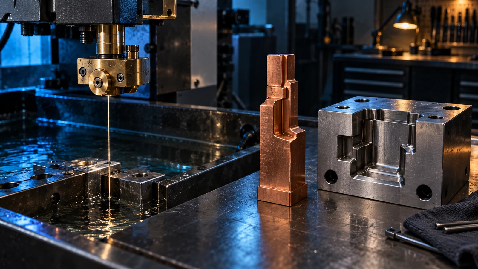
The geometry decides before the machine name
Start with a section view and ask whether the desired cut passes through the stock or stops inside it. A through-profile, narrow slit, or intricate contour is a natural wire EDM question. A recessed cavity, blind pocket with an internal shape, or form that cannot be entered by a wire path may point toward sinker EDM or another process. This distinction is not simply “wire is more precise” or “sinker is more flexible.” Both processes have setup, electrode or wire behavior, flushing, overcut, and inspection considerations. A geometry that appears machinable in a CAD view may still lack a feasible start hole, wire thread path, flushing route, or support surface. The process review should occur before a final tolerance is assigned. Jucheng’s CNC site lists wire EDM cutting. This article compares process families to help define a part requirement; it does not claim that the site provides sinker EDM.
Wire EDM and sinker EDM side by side
| Domanda | Elettroerosione a filo | Elettroerosione a tuffo |
|---|---|---|
| Typical geometry | Profiles and features cut through conductive stock | Blind or recessed cavities formed by an electrode |
| Tooling form | Continuously fed wire follows the programmed path | Electrode shape and wear influence the cavity |
| Access condition | Requires a path through the part and a practical wire-entry method | Requires electrode access and a way to flush debris from the cavity |
| Design question | Can the part be threaded, supported, and cut without losing the required profile? | Can the electrode reach the cavity and reproduce its detail with the required wear compensation? |
| Evidence to define | Profile, corner condition, cut sequence, surface integrity, and inspection datums | Cavity form, depth, electrode strategy, surface integrity, and inspection access |
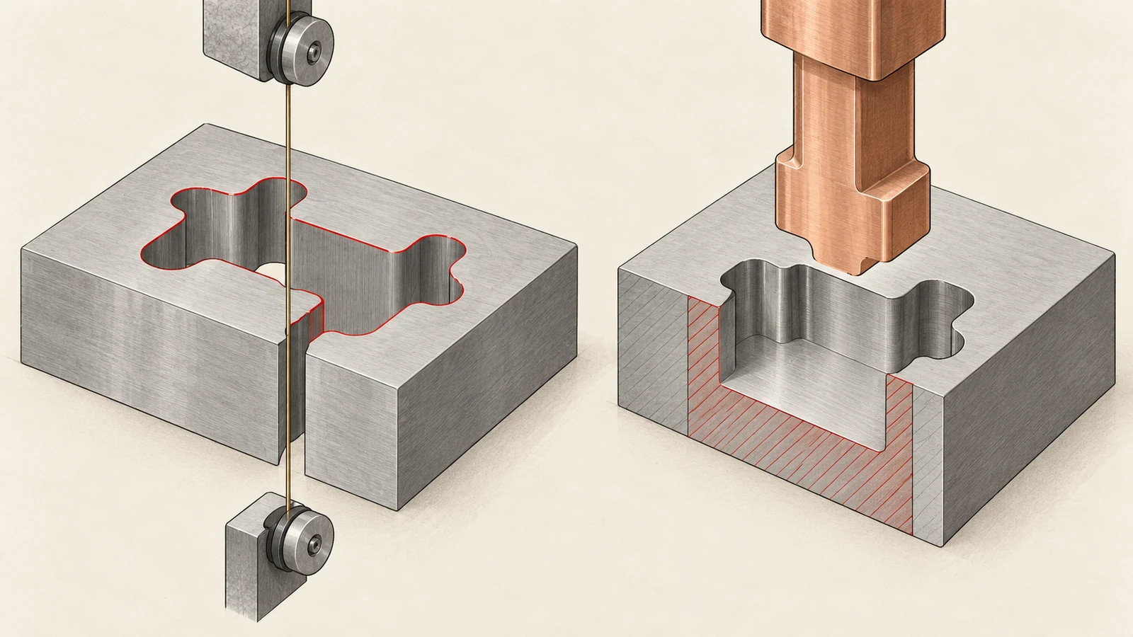
The table is a first screen, not a capability promise. Actual cycle time and achievable geometry depend on material, thickness, feature size, flushing, setup, machine condition, and the agreed inspection method. A process vendor should review the geometry and acceptance criteria before quoting an unqualified tolerance.
Check entry, access, and the parting line
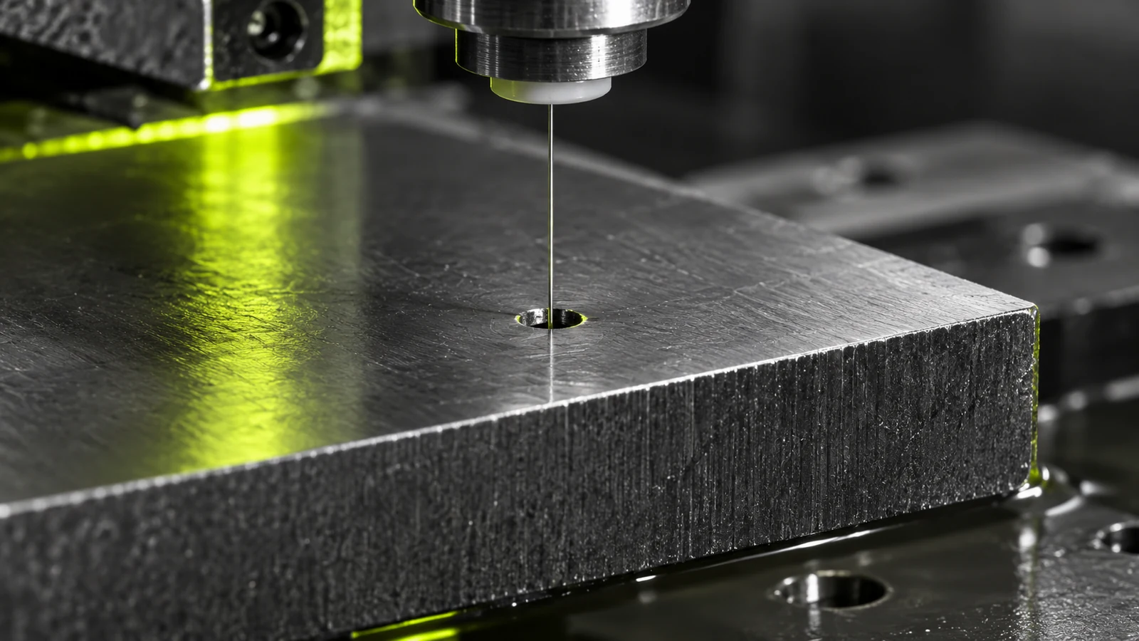
For wire EDM, determine how the wire begins the cut. A start hole may be required for an internal profile, and its location can affect the finished edge or a mating feature. Consider how the part is supported when the cut releases a slug or separates a thin section. If the cut creates a free piece, the drawing and process plan should make retention and inspection practical.
For sinker EDM, a deep or narrow cavity may restrict electrode access and flushing. Internal corners, aspect ratio, taper, and details that are smaller than the electrode’s stable geometry can create trade-offs in cycle time, electrode wear, and achievable detail. A sharp internal corner on the drawing does not mean a physical zero-radius corner will result. Workpiece thickness also changes the conversation. For wire EDM, a tall cut can raise concerns about flushing, taper, wire behavior, and how the profile is measured over height. For sinker EDM, cavity depth and narrow openings can make debris removal and electrode wear more significant. These are not reasons to replace a design requirement with a generic rule; they are reasons to review the actual cross-section with the supplier. Include datums that can be established on the EDM setup and reused during final inspection. If the EDM feature must align with milled, drilled, or turned features, state the relationship explicitly and identify when it is checked. A good-looking EDM surface is not evidence that its position to another feature is correct.
Surface integrity is part of the route
EDM creates a thermally affected surface. Depending on material and parameters, the process can leave a recast or altered layer, and additional finishing passes or post-processing may be specified. Surface roughness alone does not prove that a recast layer is absent or that the surface is suitable for fatigue-critical, sealing, or wear-sensitive use.
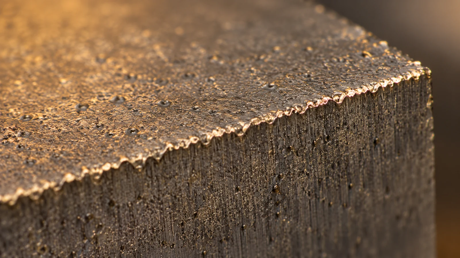
State the requirement in terms of function and evidence. Is the concern profile accuracy, roughness, a layer condition, fatigue performance, corrosion, or a particular downstream coating? Each requires a different acceptance method. If the drawing only says “smooth,” the supplier and buyer may mean different things. Likewise, avoid copying a generic Ra or tolerance number from a machine brochure. The required value should be attached to the actual surface and measured under a defined method, location, direction, and condition. If the component is later ground, lapped, polished, or coated, assign stock allowance and responsibility for verifying the final interface.
Specify the EDM result, not just the process
An RFQ for an EDM feature should include:
- current CAD model and dimensioned drawing, including units and revision;
- material grade, heat-treatment condition, and stock thickness;
- through-profile versus blind-cavity definition, entry/start-hole constraints, and any no-cut zones;
- critical profile, position, corner, taper, and datum relationships;
- surface-integrity, roughness, cleaning, and post-process requirements, if applicable;
- quantity, inspection report expectations, and whether the part is a prototype or repeat build.
Ask the supplier to identify the proposed process route and any geometry that should be adjusted before release. For a supplier offering wire EDM but not sinker EDM, that boundary should be stated directly; an article explaining the comparison must not be mistaken for a promise to supply both processes.
EDM route FAQs
Can wire EDM create a blind pocket?
Wire EDM normally follows a path through the workpiece, so a closed blind cavity is generally not a straightforward wire-cut feature. A different route, such as sinker EDM or another process, may be considered after reviewing the geometry.
Does sinker EDM only machine non-through cavities?
It is commonly selected for cavities and forms that a wire cannot traverse, but process suitability depends on electrode access, flushing, material, and required geometry.
Does a low roughness value confirm there is no recast layer?
No. Roughness and surface integrity are different acceptance questions. Specify the evidence required for the application.